


Our Guarantees Our Quality Standards Our Fair Use Policy
Why Is United kingdom Essays Different?
- There exists a verifiable buying and selling history like a United kingdom registered company (details at the end of each and every page).
- Our Nottingham offices are available to the general public where one can meet we well over 40 full-time staff.
- United kingdom Essays partner with Feefo.com to write verified customer testimonials – both negative and positive!
Ask a specialist FREE
Ask a specialist Index Ask an issue Compensated Services
About Our Ask a specialist Service
Our free of charge “Ask a specialistInch Service enables users to obtain an answer as high as 300 words to the academic question.
- Questions typically clarified within 24 hrs.
- All solutions are researched and compiled by properly accredited academics within the question’s area of interest.
- Our services are completely private, only the reply is printed – we never publish your individual details.
- Each professional answer includes appropriate references.
About Us
Much More About Us
Essay Writing Service
Introduction
The Formula Student is really a competition that’s organized the Institution of Mechanical Engineers (IMechE) in colaboration with the Society of Automotive Engineering (SAE) between groups of students from various universities to create, build and market just one seater sprint race vehicle. College of Leeds has become in the 13th year of participation using the F12 to race in California this season and also the F14 that’ll be produced by the finish of the present academic term. The F14 has been made to add a four stroke, single cylinder Yamaha KTM engine than the 4 stroke engine which is used within the F12.

The F10 was the final vehicle which had incorporated monocoque chassis and also the F11 was the first one to be made with a complete space frame chassis.

But because of design flaws the F11 didn’t reach competition. F12 may be the second vehicle to become designed utilizing a space frame chassis also it mainly addressed the issues within the F11 design concentrating on the same handling characteristics as F10. Presently the F12 has been enhanced because of its performance for that race this season and F14 is within its initial design stages.
AS on date the F14 chassis stands nearly complete as reported by the initial designs with no rear finish since the orientation of engine mounting wasn’t finalized through the Level 4 team. Thus it’s still not yet been made the decision. This report provides specifics of the look and computational testing from the F14 chassis having a look at what may well function as the final form of the chassis.
It will be noted the chassis is among the last aspects of a vehicle that’s made the decision because the individual components that enter in the vehicle are made the decision initially. The style of the suspension from the vehicle is one thing that’s also done hands in hands using the chassis design because you can possess a good chassis but most likely of low quality suspension geometry to choose it and the other way around. The very best combination is achieved when they’re modelled concurrently.
It’s also significant the project progresses in the Level 3 to Level 4 once the understanding of chassis structures, suspension geometry is furthered some aspects of the present chassis are susceptible to modification. This may involve inclusion or exclusion of certain people, moving of certain people etc.

Aims Objectives
2.1 Aims
The work aims to computationally design, evaluate, and test a brand new chassis for that Leeds Formula Student Vehicle F14. Included in this are gaining helpful understanding of the formerly done work and organize that understanding to become implemented in to the new vehicle to become developed and effectively transfer all of the understanding for that students to operate around the future versions from the vehicle.
The larger picture for that college would be to finish with be among the very best and finest competitors within the competition within the various occasions inside the overall competition.
2.2 Objectives
The important thing qualifying criterion for that effective performance of the chassis is its torsional stiffness. As proven within the table above, plain carbon steel has greater specific stiffness and it is easy to utilize during manufacturing process. Hence it’s the apparent choice.
Mass qualities of F14
Output coordinate System: — default —
Density = 7.8e+003 kilograms per cubic meter
Mass = 31 kilograms
Volume = 3.97e+006 cubic millimeters
Area = 3.96e+006 millimeters^2
Center of mass: ( millimeters )
Principal axes of inertia and principal moments of inertia: ( kilograms * square millimeters )
Taken in the center of mass.
Ix = (-1.97e-005, -.0798, .997) Px = 2.69e+006
Iy = (-.000265, -.997, -.0798) Py = 1.43e+007
Iz = (1, -.000265, -1.44e-006) Pz = 1.45e+007
Moments of inertia: ( kilograms * square millimeters )
Taken in the center of mass and aligned using the output coordinate system.
Lxx = 1.45e+007 Lxy = 81.4 Lxz = -228
Lyx = 81.4 Lyy = 1.42e+007 Lyz = -9.24e+005
Lzx = -228 Lzy = -9.24e+005 Lzz = 2.76e+006
Moments of inertia: ( kilograms * square millimeters )
Taken in the output coordinate system.
Ixx = 2.62e+007 Ixy = -65.5 Ixz = -391
Iyx = -65.5 Iyy = 2.06e+007 Iyz = 4.85e+006
Izx = -391 Izy = 4.85e+006 Izz = 7.99e+006
Results
Torsional Test Method 1
The position of twist was calculated at 12 points along the size of the chassis. They’re labelled 1 to six from right to left along the size of the chassis. The deflections at the blue marked locations were chosen for that calculation from the deflection position within the structure.(Figure 8)
Figure 8- Deflection measurement locations across the chassis
As possible see, our prime stress concentrations are right in front bulkhead region. And also the stresses reduce within the regions along the size of the chassis. This simulates an abrupt bump throughout the cornering from the vehicle. (Figures 9 and 10)
Maximum stress plot.digital
Figure 9- F14 method 1 high stress areas
Figure 10- F14 maximum stress location
This process yields a torsional stiffness worth of 2451Nm/. And also the specific torsional stiffness is calculated to become 79.1Nm/0Kg fir the 31Kg chassis of F14.
Torsional Test Method 2
This process yields a torsional stiffness worth of 2530N/ that is 1.5 occasions the calculated worth of F12. The particular torsional stiffness value is calculated to become 81.1 Nm/0Kg that is 2% greater compared to formerly calculated result.
Discussion
Torsional Test
As reported formerly within the Level 3 report of the style of Chassis, the technique of feeding the forces in to the suspension points provides a better picture from the torsional stiffness.
The need for torsional stiff that people obtain is basically determined by the kind of way in which we use to calculate it. Within this situation two different ways were considered for that calculation of torsional stiffness and clearly one of these shows quality value of 2530Nm/ having a specific worth of 81.1Nm/0kg as the other provides a worth of 2451 Nm/ having a specific stiffness of 79.1 Nm/0Kg.
Clearly we are able to visit a difference of two.4% within the values. Therefore we can conclude that any of these two methods is a great one for calculating the torsional stiffness from the chassis.
It wasn’t really feasible for accurate comparisons from the previous year’s data and also the present computational results since there wasn’t any decisive decision concerning the model which was studied. As well as because of the insufficient a few of the information which was required for the effective completion wasn’t available the present report couldn’t achieve an apt comparison towards the results acquired.
Conclusion
The present study couldn’t decide precisely the accurate means of the resolution of torsional stiffness. The computationally calculated worth of the torsional stiffness in our study is 2530Nm/ having a specific torsional stiffness worth of 81.1Nm/0Kg.
Bibliography
Lance armstrong, C.G. Benham, P.P. and Crawford, R.J. 1996. Mechanics of engineering materials. second edition. Kent: Pearson Education Limited.
Callister, W.D. Jnr. (2000). Materials science and engineering: An intro. fifth edition. Chichester: John Wiley and Sons Limited.
Costin, M. and Phipps, D. (1967). Racing and sports vehicle chassis design. Massachusetts: Bentley, Corporation.
Kraige, L.G. and Meriam, J.L. (1993). Engineering mechanics: Volume one. 3rd edition. Chichester: John Wiley and Sons Limited.
Matthews, C. (2004). Engineers’ data book. 3rd edition. Chichester: John Wiley and Sons Limited.
Milliken, D.L. and Milliken, W.F. (2002). Chassis design: Concepts and analysis. Warrendale: Society of Automotive Engineers, Corporation.
Milliken, D.L. and Milliken, W.F. (1995). Race vehicle vehicle dynamics. Warrendale: Society of Automotive Engineers, Corporation.
Robert Bosch Limited. (2007). Automotive guide. seventh edition. Plochingen: Robert Bosch GmbH.
References
Request Removal
If you’re the initial author of the essay with no longer want the essay printed around the United kingdom Essays website then please click the link below to request removal:
More from United kingdom Essays

 Capacitor less ldo thesis proposal
 Online membership system thesis proposal
 The slave ship marcus rediker thesis proposal
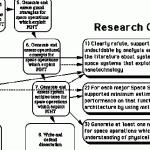 Research proposal sample for thesis
 Mother tongue essay thesis proposal


