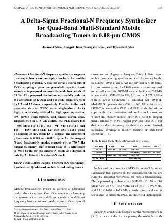
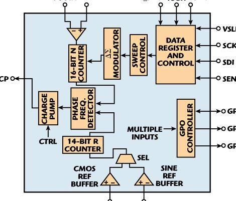
This model shows how you can simulate a phase-locked fractional-N frequency synthesizer. The model multiplies the regularity synFr of the reference signal with a constant synN+synM. to make a synthesized signal of frequency synFr(synN+synM). A feedback loop maintains the regularity from the synthesized signal only at that level. Within this example, synN is definitely an integer and synM is really a fraction between and 1. This method has lots of advantages, because it allows you to approximate the regularity from the synthesized signal with relatively small values for synN and synM .
Fractional-N PLL synthesizers achieve improved frequency resolution at the fee for elevated circuit complexity and elevated phase noise (timing jitter) over their non-fractional counterparts. Additionally, it enables using a bigger reference frequency. To learn more, see Selected Bibliography. This model implements a fractional-N plan with analog phase error correction within the phase detector area of the design. This eliminates the sidebands created by switching the loop divider between N and N+1.
There’s a less complicated example available, PLL-Based Frequency Synthesis Example. which creates a synthesized signal of frequency synFr*synN/synM. where synN and synM are integers.
Structure from the Example
The model uses these variables additionally to synN and synM:
synFr – frequency from the reference signal
synFq – quiescent frequency within the Continuous-Time VCO block
synSen – Current-Controlled Oscillator input sensitivity
The model initially assigns values to those variables the following:
synSen = 10 MHz/V
The regularity from the synthesized signal in the model’s steady condition will be 103 MHz. After running the simulation using these values, you are able to later change them by typing new values within the MATLAB® Command Window, if you wish to test out the model.
Blocks and Subsystems within the Example
Most of the blocks within this model function in the same manner because they do within the PLL-Based Frequency Synthesis Example. This discusses the subsystems which are different.
Accumulator: The Accumulator subsystem frequently adds the continual synM to some cumulative sum. As the sum is under 1, the output labeled Carry is . At any given time step once the sum becomes more than or comparable to 1, the carry output is 1 and also the cumulative sum is reset to the fractional part. The fraction of times once the carry output is 1 is equivalent to synM. as the fraction of times when it’s is equivalent to 1-synM. The accumulator controls the switching between N and N+1 using the carry output. The accumulator output (condition) can be used they are driving the phase compensation circuitry.
Divide Frequency: Divide by N or N+1 is implemented utilizing a “swallow” counter plan, because it would probably be completed in hardware. The Divide Frequency subsystem divides the regularity from the synthesized signal by synN once the creation of the Accumulator subsystem is , and divides it by synN+1 once the output is 1. Consequently, the typical value the frequency is split by is
(1-synM)*synN + synM*(synN+1) = synN + synM = 10.3
Phase Detector: Phase-frequency detector and error compensator utilizes a “dual D” switch-flop for phase recognition, with an integrator, Sample and Hold block, and a straightforward lead/lag loop filter for error compensation.
Results and Displays
Advertising media are the simulation listed here are the Scopes which are displayed:
Control Signals Scope:
The control signal, that the VCO block uses to keep the regularity from the synthesized signal
The VCO Control signal: This really is seen to stay to some stable value with Phase compensation set to ‘on’ (default)
Synthesized Signal Scope:
The square wave generated in line with the VCO output
RF Spectrum Analyzer Spectrum Scope:
Displays the regularity spurs.
Going through the Example
The switch labeled ‘Phase Comp Enable’ is placed to ‘on’ automatically. Within this mode timing jitter and sideband frequency spurs are totally eliminated with only just one frequency spur of -80 dB remaining.
Run the simulation using the compensation off: switch in lower position. The graphs can have significant phase jitter and sidebands because of the periodic variations from the VCO control current.
The Simulink model outputs an excellent quality synthesized output. Real life component limitations is now able to brought to study their effects around the system performance.
Selected Bibliography
Egan, William F. “Fractional-N and Relatives”, Frequency Synthesis by Phase Lock. (second erectile dysfunction. pp. 371-390). N.Y. John Wiley Sons, 2000.




 I am writing my master thesis
 Writing a discussion section of thesis definition
 Laser doppler anemometry thesis writing
 Writing acknowledgements for thesis outline
 Sample specific problem in thesis writing
