Our Guarantees Our Quality Standards Our Fair Use Policy
What Makes UK Essays Different?
- We have a verifiable trading history as a UK registered company (details at the bottom of every page).
- Our Nottingham offices are open to the public where you can meet our team of over 40 full-time staff.
- UK Essays partner with Feefo.com to publish verified customer testimonials – both good and bad!
Ask an Expert FREE
Ask an Expert Index Ask a Question Paid Services
About Our Ask an Expert Service
Our totally free “Ask an Expert” Service allows users to get an answer of up to 300 words to any academic question.
- Questions typically answered within 24 hours.
- All answers are researched and written by fully qualified academics in the question’s subject area.
- Our service is completely confidential, only the answer is published – we never publish your personal details.
- Each professional answer comes with appropriate references.
About Us
More About Us
Published: 23, March 2015
The main aim of this lab is to get exposed to classical method and applications of a laser Doppler anemometry. This illustrates how to align and optimise optical system, how to calculate beam angle and optical fringe spacing, how to measure MCV parameters in different mediums, how to measure different focal lengths.
Laser Doppler Anemometry (LDA), also known as Laser Doppler Velocimetry (LDV) is a modish optical technology to measure, more specifically the velocity of particle in a fluid flow. Science and engineering industries apply LDA optical technology to study mechanics of fluid in detail .This optical technology is ideal for point measurement of velocity in non-intrusive, 1D, 2D, 3D flows.
Calibration in the usual manner is not so important, length and frequency measurements suffice to calculate velocity at a spatial point. Below given figure-1 illustrates an ideal laser Doppler anemometry setup.
LASER stands as an acronym for light amplification by stimulated emission of radiation. The basic technique behind it is, light gets scattered due to the particles in the flow and pass through a pattern of interference fringes (a pattern of light and dark surfaces).
Professional
Get your grade
or your money back
using our Essay Writing Service!
Essay Writing Service
The working of a laser is a simple process, the electrons are excited by raising energy levels to produce photons which inturn reproduce photons by colliding with other molecules and excite them, resulting in a ‘Deluge’ of photons .Thus a beam of high degree of spatial and highly coherent light is produced. Instead of normal light sources, only lasers are used in Incandescent lamp, due to its high coherent, monochromatic, polarised properties.
Lasers are classified into four classes, depending upon its wavelength, hazards, apertures, emission etc. A class-1 laser is safe for normal use under all conditions and class-4 lasers have greater power and high risk factor. Class-2 and class-3 are also not considered as safe, unless they are handled carefully, with high precautions and restricted beam viewing.
Laser beam is split into two beams by interfering it with a splitter, to ensure wave fronts in a laser beam are stepwise.
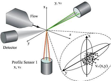
This laser beam will pass through a focusing lens and changes its direction to coincide at one point, which is defined as a measurement control volume (MCV).
The frequency of a particle in a flow, which crosses through MCV, can be calculated by
Were, Ux – perpendicular component of velocity.
– Wavelength (Gaussian beam property).
Half angle at intersection of two laser beams.
The wave length of the laser is accurately predefined, only half angle intersection () should be found out using length and distance as shown in fig 11 with given below formula
The measurement control volume contains a no of fringes, distance between interference fringes are calculated by using below formula
Thus the velocity component perpendicular to the interference fringes of a particle in the mcv equals to frequency multiplied by distance between two points on screen.
Were, fD – Signal frequency
– Distance between fringes (units -)
The width of the measurement control volume is calculated as, no of visible fringes multiplied by distance between fringes.
Width of MCV = Nf .
A Doppler signal is a combination of high and low frequency, were low frequency are called as Gaussian envelope and high frequency are produced from the particle that passes through MCV.
The application of filters is to get a frequency symmetric about the centre line with Doppler signal can be found. Thus frequency filters are used to filter out the low frequencies, resulting in finely tuned modulation depth. This ranges between 0-1 and noted as Vmin and Vmax which form a relation of:
An ideal doppler signal has a modulation depth of unity (). Commonly we cannot perform an Ideal Doppler experiment due to following reasons:
Beams exhibit unequal orientation and are not linearly polarised.
Intensities of beams are not equal.
Partial intersection of beams.
Fringe spacing is radically smaller than the size of particle.
The aim is to obtain high signal amplitude, visibility and high data rate; this can be obtained by adjusting the APD and filters.
EXPERIMENTAL APPARATUS
A laser beam producing setup.(fig-2)
Comprehensive
Plagiarism-free
Always on Time
Marked to Standard
Figure-2 laser optical unit
A beam stops (mask) to stop extra super flow beams.(fig-4)
A green plastic sheet to capture Measurement Control Volume (MCV).(fig -3)
Fig -3 plastic sheet
Receiving lens.(fig -3)
Fig -3 receiving lens and mask
Observatory white screen board. (fig-5)
Fig-5 white screen board
Avalanche Photo Diode (APD) in association with filters, which is connected to a Digital Storage Oscilloscope.(fig-6)
Fig-6 Digital oscilloscope
Rectangular tank filled with water
Figure-8 rectangular water tank
Measuring metal tape.
Figure-9 metal tape
Fig-9 ruler marker
EXPERIMENTAL PROCEDURE
The green plastic piece is positioned away from laser setup, were MCV is obtained. The distance (D) between two lasers spots on screen and length (L) between plastic piece to screen are measured using a metal tape or ruler. This are substituted in. i.e. beam angle is calculated. Beam angle is taken as mean of all measurements. This helps us to calculate fringe spacing =. wave length of laser beam is given as 0.632 .
A new setup is created for measurement of MCV dimensions by positioning a projecting lens to obtain laser spots on the screen. This lens is moved until spots get interfering initially; keep on moving until this spots leave each other. Position of lens for both initial interference and final are marked and measured. Thus length of the MCV is equal to difference in this measured length. The fringes are clearly visible when both the spots get completely interfere (a pattern of red and black thick lines will be seen). Thus no of visible fringes in 10 mm of length are counted and multiplied with fringe spacing to obtain width of measurement control volume(MCV) using the formula:
Nf = no of fringes X length of laser beam
The piece of green plastic was placed at the MCV and receiving lens is moved in the axial direction until both the beams were blocked by black strips. To obtain a sharp MCV image, the APD was adjusted. The effect of moving the green plastic in the axial direction back forth was observed. Finally, the 2 screws on the apd were adjusted until the MCV image was aligned with the pinhole of the APD.
To optimize the optics, distances L and l were measured the values were compared using young’s thin lens equation.
An optimum magnification factor m was determined in order to have diameter properly image on the APD pinhole. m can be calculated as
Position of L of the lens was found.
To capture the doppler burst signal, the APD signal cable was connected to a digital storage oscilloscope. The apd was adjusted accordingly to measure the signal modulation depth at several distance of Land l.
The distance between the MCV and the receiving lens is changed in steps of 5cm, while the modulation depth at each step recorded. To obtain highest visibility value an estimated distance was taken while comparing the distances L and l in the previous table.
Same experiment is repeated from step 1 again with water as a medium. The factor of change in displacement and position are calibrated and discussed. Snell’s law is used to prove that interference spacing remains same in both mediums (water air). Thus an error analysis is done using ‘square root of the squares’ method on dimensions of MCV.
CALCULATIONS
The half angle between two beams is calculated by using formula
The values of distance, length are measured and tabulated as below.
No
Showing result 1 – 5 of 28 swedish dissertations containing the words laser-Doppler anemometry.
1. Fluid and Solid Particle Dynamics in Stirred Vessels
University dissertation from Chalmers University of Technology
Abstract. The present thesis deals with the fluid dynamics of stirred vessels and particularly those that are to be used in conjunction with solids suspensions. Stirred vessels are very common in the process industry and large amounts of energy can be saved by optimising their operation. READ MORE
2. Experimental study of turbulent flows through pipe bends
University dissertation from KTH Royal Institute of Technology
Abstract. This thesis deals with turbulent flows in 90 degree curved pipes of circular cross-section. The flow cases investigated experimentally are turbulent flow with and without an additional motion, swirling or pulsating, superposed on the primary flow. READ MORE
3. Applications of Laser Based Measurements to Combustion Related Fluid Dynamics
University dissertation from Division of Thermal Power engineering, Lund Institute of Technology. Box 118, S-221 00 LUND, Sweden
Abstract. This thesis is concerned with laser based techniques for the measurement of fluid dynamical properties and their application to combusting flowfields or flowfields related to combustion. As an introduction, the theory of turbulent flows and combustion is shortly presented. An overview of laser based measuring techniques is given. READ MORE
4. Turbulent Shear Flow Experiments: Design of Natural Convection Rig and LDA Measurement in Swirling Jets
University dissertation from Chalmers University of Technology
Abstract. This work consist of two sections. In the first part, a facility has been installed and modified from an existing rig in order to measure velocity and temperature field of axisymmetric turbulent natural convection boundary layers. With using laser doppler anemometry and cold wire resistance thermometry. READ MORE
5. Experimental Studies of Effusion Cooling
University dissertation from Chalmers University of Technology
Abstract. The desire to increase the efficiency of jet engines, has led to an increase in the temperature in the combustion chambers and in the turbine stage. There is thus an interest in efficient cooling methods. Film cooling and effusion cooling are often used where there is a great heat load. READ MORE


 Critical analysis sample thesis proposal
 Leerstijlen van kolb thesis proposal
 Method of writing references in thesis writing
 Action research doctoral thesis writing
 Thesis for self reflective essay on writing
