Our Guarantees Our Quality Standards Our Fair Use Policy
Why Is United kingdom Essays Different?
- There exists a verifiable buying and selling history like a United kingdom registered company (details at the end of each and every page).
- Our Nottingham offices are available to the general public where one can meet we well over 40 full-time staff.
- United kingdom Essays partner with Feefo.com to write verified customer testimonials – both negative and positive!
Ask a specialist FREE
Ask a specialist Index Ask an issue Compensated Services
About Our Ask a specialist Service
Our free of charge “Ask a specialistInch Service enables users to obtain an answer as high as 300 words to the academic question.
- Questions typically clarified within 24 hrs.
- All solutions are researched and compiled by properly accredited academics within the question’s area of interest.
- Our services are completely private, only the reply is printed – we never publish your individual details.
- Each professional answer includes appropriate references.
About Us
Much More About Us
Printed: 23, March 2015
Synchronous reluctance machines really are a early electric machine with simplest mechanical structure. Formerly it had been referred to as self beginning synchronous machine due to beginning ability from line current and lock into synchronous speed. The majority of the machines to the 1970s specified for as direct-on-line start machines [2]. They had poor performance because of beginning cage and utilized in Textile industry. Until 1980s researchers community overlooked this kind of machine, because of inappropriate control technology, and poor performance (e.g. power factor, torque per unit volume) with rival other ac machine especially induction machine. To enhance performance of SynRM, a number of studies have been conducted from last 30 years concentrating on machine design, motor control strategy including sensor or sensor less technique.
The performance of SynRM depends upon saliency ratio. High saliency ratio is possible by maximizing the number of d-axis inductance to q-axis inductance [4]. A beginning cage less SynRM design could be created for high saliency ratio [3]. Because of the improvement of rotor structure and stator winding configuration have elevated potential of SynRM.
Professional
Get the grade
or a refund
using our Essay Writing Service!
Essay Writing Service
However, the control formula of these machines is very complicated and needs high computational power which computers and particularly microcontrollers were not able to supply previously. Nowadays, advanced microcontroller and FPGA technologies can manage the charge of they. Consequently, the eye of researchers, developers and manufacturers in reluctance machines grows at rapid paces. Within the focus of the study is analysis and growth and development of control technique for RSM.
The Synchronous Reluctance Motor
Synchronous reluctance motors are rugged, robotically simple in structure, and cheaper to fabricate compared to other kinds of AC machines [4].
The primary options that come with SynRM are [5]
No magnet in Rotor
Independent relationship between temperature and torque per ampere
Stator construction much like IM
Simpler implementation of FOC than IM
Cage less structure
2.2 Fundamental Operating Principle
A typical approach to energy conversion from electrical to mechanical is dependant on electro-magnetism. This is actually the generally used method right from the start in history of electrical motor. Normally, two magnetic fields interacts one another and fosters torque on rotor. However the principle of Reluctance motor differs from other kinds of motor (e.g. IM, PMSM).A magnetic field in mid-air gap could be created by making use of exciting currents towards the stator windings. Whenever a source of energy is used in stator,
Whenever a magnetic field is created in mid-air gap by making use of exciting currents towards the stator windings. The rotor will make an effort to align its most magnetically conductive axis, the d-axis, using the applied field, to be able to minimize the reluctance within the magnetic circuit[6].
Fig 1: Conceptual diagram of reluctance machine [19]
2.3 Stator Construction
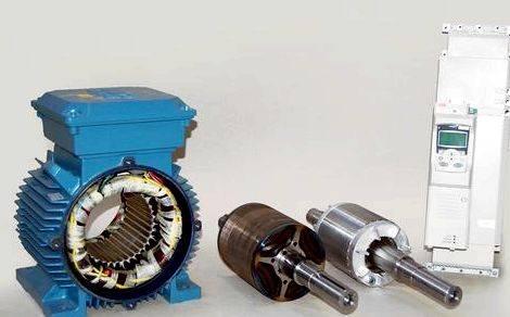
The 3-phase stator winding have reached the graceful but slotted stator bore. To be the stator’s purpose to make a sinusoid ally distributed mmf wave, its structure is virtually just like to have an induction motor [7].A typical ploy phase arrangement uses in stator construction of Synchronous reluctance motor. A 3 phase current source is used at stator terminal to create magnetic flux inside motor stator. These magnetic flux attracts rotor to rotate with synchronous speed [8] .Flux linkage is directly proportional to stator current. So, Torque could be controlled by stator current.
Fig 2: SynRM stator
2.4 Rotor Construction
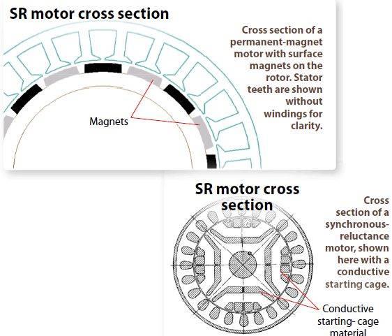
A several studied continues to be performed on rotor construction especially on rotor shape. The fundamental idea would be to identify a shortest path for stator created magnetic flux through rotor. A SynRM might have various rotor configuration for example transversely laminated (Fig 3), axially laminated anisotropic (ALA). The saliency from the machine is achieved by punching flux barriers in to the laminations in situation of transversely laminated rotor. This kind rotor has poor structural characteristics, and never appropriate to function in high-speed in existence of high centrifugal pressure [9].
Another type is Axially-laminated anisotropic (ALA) design (Fig 4).It features a similar mix section towards the transverse laminated design. Axially-laminated rotors contain layers, or laminations, of (soft) magnetic and nonmagnetic materials in which the nonmagnetic layers supply the requisite ¬‚ux barriers.
Comprehensive
Plagiarism-free
Always promptly
Marked to plain
Generally, the nonmagnetic materials are also an electrically efficiency which impedes the flow of eddy currents within the rotor. This type of rotor produces road to maximum permeance in direction of the laminations (d-axis direction) and minimum permeance within the direction normal towards the laminations (q-axis direction). By doing this a higher saliency ratio is achieved, which leads to improved performance [8],[10].
Fig 3: Transverse laminated rotor
Fig 4: Axially-laminated anisotropic (ALA) rotor
Theory of Synchronous Reluctance Motor
The SynRM considered here includes a ALA rotor type, without any permanent magnets and windings around the rotor.
A precise motor model depends upon the systematic calculation of motor parameters. The mathematical model is important for simulation of the system. In SynRM rotor doesn’t contain any winding. So, motor model depends on only stator.
3.1 SynRM model in three phase (U, V, W) Reference frame
In SynRM, Three phase equations can be defined as [15], [16]:
Where, are motor phase voltages Stator winding resistance are three phase flux linkage.
Now, flux linkage could be expressed as
Thinking about as much as second order harmonics, each self and mutual inductance are
Where, Leakage inductance from the phase.
Where, d-axis equivalent air gap q-axis equivalent air gapRotor radiusCore length Quantity of turns in series per phase.
Assume machine is symmetric and taking advantage of the 3 phase to 2 phase transformation
Where would be the two phase’s voltages, currents and flux in stationary reference frame.
Flux calculation in stationary reference frame as follow
Where motor flux
Rotor reluctance causes the motor torque ().
Where Quantity of motor rods.
3.2 SynRM model in d-q Reference frame
The electrical area of the SynRM could be explained the next well-known current equations within the d-q reference frame [17]:
Where Speed of rotor direct axis inductance q-axis inductance Stator winding resistance per phase.
The electromagnetic torque could be expressed as
The equation () could be re-written as
Inductance Calculation Method
Many researches happen to be conducted for theoretically parameter estimation (e.g. inductance) of SynRM. Several inductance calculation methods exists for preliminary design purposes. They are Analytical (e.g. crude) method, Coupled magnetic circuit (e.g. Full order) method, Finite element method.
Among individuals methods, we’ll use Analytical way of inductance calculation that is time intensive kinds of method.
3.1 Coupled magnetic circuit for inductance computation
A precise self- and mutual – inductances calculation is going to be useful to carry out a better research into the SynRM. There are many analytical method open to calculate self- and mutual- inductances from the SynRM.
3.1.1 Full-order model
This model is dependant on winding function theory. In 1965, Winding function theory was initially employed for magnetic inductance calculation which gave an answer of coupled electro-magnetic equations [12].
Full order model refers back to the utilization of real machine geometry such as the stator slot openings and also the insulation separation between rotor axial laminations, and winding placement patterns and positions. Winding functions theory may be used to calculate inductances including all harmonics. Air gap length is recognized as variable purpose of air gap flux [13].
Fig. 5 axially laminated rotor structure
Using Fourier series, a random phase of the -phase machine with pole pairs the Winding Function is
Where for phases A, B, C correspondingly, Harmonic order, Quantity of pole pairs,quantity of phases, Quantity of turns pole per phase.
The formula for calculating -Th Harmonic winding factor,
Distribution factors, Pitch factors, Pole pitch, Coil width, Quantity of slots per pole per phase.
The environment gap function for ALA (Axially laminated anisotropic) is suggested by Bianchi and Chalmers [16]
Effective radius Rotor angular position = Carter’s coeffcient Air gap at pole face.
Phase Inductance calculation:
Where Motor stack length, Air gap function, Angular distance in between each subdivision in mechanical radians.
A leakage inductance is going to be added with phase inductance to acquire self inductance. The inductance matrix is
This Essay is
This essay continues to be posted with a student. This isn’t a good example of the job compiled by our professional essay authors.
Types of our work
A Park’s transformation matrix can be used to calculate inductance values in rotor reference frame
Where, . ..(7)
This report presents a brief discussion about analytical inductance calculation method,
the historic growth and development of SynRM, abc reference model, d-q model. The motor model was created by utilizing Matlab/Simulink software program. Also, an inductance calculation method was fully discussed within this report. This process may be used other ac motor. This process is simple and fewer time intensive with rival FEA.
The discussed technique is no more accurate, it ought to be improved to better model.
A appropriate controller ought to be made to evaluate motor performance in variant speed range.
Request Removal
If you’re the initial author of the essay with no longer want the essay printed around the United kingdom Essays website then please click the link below to request removal:
More from United kingdom Essays




 Data gathering tools sample thesis proposal
 Topics in psychology thesis proposal
 Anti-fischer a new war-guilt thesis proposal
 Introduire une conclusion dans une dissertation proposal
 Jlab hall b thesis proposal
