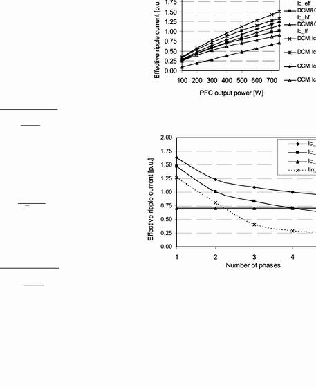
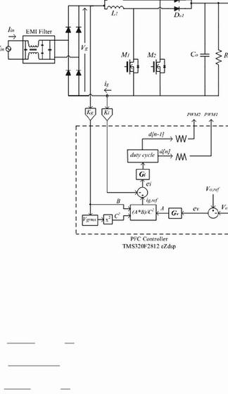
As it’s known, there are two types of DC-DC converters, isolated and non isolated, so that the main difference between them is the use of a transformer. In this project there is no requirement in respect of such feature so we chose to use a converter that is not isolated. There are several types of non-isolated converters, the most common are Buck, Boost, Buck-Boost, Cuk and Sepic. If we want to have an output voltage higher than the input boost converter is the ideal choice, however this type of converter produces at its output very high ripple current which will conflict with the demands made at the beginning of the project. So the solution is an Interleaved Boost converter which uses more than one phase to generate an output current with low ripple. You can see in Figure 5 the converter dimensioned to fulfill the requirements. This design makes use of simulation software like MATLAB and PSIM that use tools like Simcoupler allowing the interaction of these two software more efficient and intuitive from the standpoint of analysis. This system was simulated for three types of constant radiation(Fig. 8), ramp (fig. 9) and step (fig. 10), and we can conclude from the last simulation (the step) that the MPPT algorithm needs calibration observing that the extracted power doesnt match with the maximum power available.
Fig.5 – 2-Phase Interleaved Boost Converter
There are several algorithms for tracking power, the main ones are explained in the state of art of this project, namely Incremental Conductance, Observe and disturbing, Constant Voltage, Fuzzy and Neural networks. After thorough study of these different methods is concluded that the most appropriate would be in initial phase the method of incremental conductance, it is a stable algorithm, which tends to produce good results quite quickly.
After successful implementation of this method and respective analysis would be interesting to implement another method associated with this to produce an hybrid algorithm based on two different methods. However at an early stage will used the incremental conductance method which methodology should be slightly modified to produce an output as duty cycle and not a reference voltage like the traditional one. You can see the flowchart of this method in fig.6 and in Fig.7 Observe and disturbing Algorithm (implemented in a more advanced phase of the project). In Figures 11, 12 and 13 it can be seen comparison between the MPPT algorithms used.
Fig.6 – Flowchart of Incremental Conductance MPPT Algorithm
Fig.7 – Flowchart of Observe and disturbing MPPT Algorithm




 Electrical engineering topics for thesis writing
 Phd thesis writing plan for kindergarten
 Writing a thesis proposal masters
 Phd thesis proposal in economics
 World hunger essay thesis writing
