Abstract
Means of adjustment of drive parameters throughout the change of control modes is presented. The techniques are put on Magnet Synchronous Motor (PMSM) sensorless control with Sliding Mode Observer (SMO). The phase compensation was suggested to optimize rotor position within the speed control mode. This method is dependant on the measurement of control up-to-date with constant load torque. The validity from the suggested methods is verified experimentally.
INTRODUCTION
Magnet Synchronous Motors (PMSM) with Field Oriented Control drives are broadly utilized in various industrial applications because of their high-power factor, high-torque density, high quality and small size. For effective use of vector-control algorithms, it’s important to understand the rotor position. Encoders or revolvers happen to be employed for sensing the rotor position. However, the positioning sensor boosts the cost and reduces reliability and noise immunity from the PMSM drive system. Therefore, vector-control methods, even without the any shaft sensors, happen to be investigated by many people researchers.
Sensorless control in field-oriented PMSM depends on dependency from the rotor position upon the rear electromotive pressure (back-EMF) caused within the stator windings [10, 11]. The estimation from the rotor position and speed (condition variables) requires using a relatively accurate motor model, the understanding from the feeding voltages (system input) and also the measurement of motor currents (system output) with waveforms proportional to back-EMF.
Several believed methods were covered in literature, which base on condition observers [1, 2, 3, 4], extended Kalman filters [5, 6] and sliding mode observer [5, 7, 8].
One of the various approaches, the Sliding Mode Observer (SMO) represents a beautiful proposal since it is robust to measurement noise, parameter deviations and also the natural high gain structure [11]. This process does not require high computational charge (as with the situation of Kalman Filter) and could be effectively implemented in low-cost controllers. However, SMO introduces time-delay within the rotor position estimation because of the utilisation of the low-pass filter to extract rotor position position from back-EMF signal. Meanwhile, this low-pass filter results in inevitable and undesirable phase lag within the rotor-position estimation. Various sensorless control schemes were suggested to enhance the precision from the rotor position estimation [8, 12, 13]. For variable speed drive, the rate and frequency of back-EMF aren’t constant. Thus, a compensation way in which can hold this case is required. Theoretically, the compensation position could be acquired directly through the phase/frequency response from the adopted low-pass filter. Actually, an additional correction is required because of various deviations of motor parameters, measurement errors, calculation delay, etc.
These studies presents a good way to compensate phase lag in SMO for that PMSM drive with close-loop velocity control. Practical recommendations were created to alter control mode instantly from beginning open-loop to shut-loop speed control.
CONTROL Plan
A typical digital vector control plan is proven in Fig. 1.
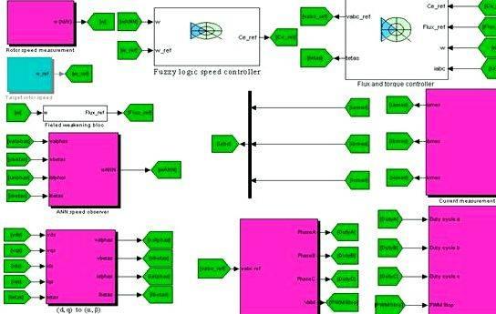
You are able to that SMO doesn’t operate normally in a really low speed and dead stop. To achieve the rate set-point, the entire start-up procedure was developed by consecutive switching from the three control modes within the following order:
- open-loop V/f speed control (switches 1 and a pair of are positioned in place 1)
- inner-loop vector current control (switch 1 is switched in place 2 and switch 2 remains occur position 1)
- outer-loop speed control (switches 1 and a pair of are positioned in place 2).
The same start-up operation for sensorless speed control was described in [15] for Kalman filter estimator. Within this paper the adjustable SMO was utilized to handle the beginning-up transient without brutal condition change throughout the mode switching.
Because of the initial step, a rotating-stator field is generated with angular velocity wop provided by the derivative from the reference position Qop within the space-vector pulse width modulation (SVPWM), with amplitude with respect to the current value iq,op. The rotor starts to move because of the attracting torque between your rotor magnets and rotating field. SMO falls right into a correct estimation mode. However, the believed rotor position Q always is different from the generated stator reference position Qop. To prevent a clear, crisp position change, the believed rotor position Q* within the creation of SMO should be forced (DQstart) towards the reference position Qop prior to the second control mode switching.
Within the second control mode PMSM reaches the certain speed which depends upon the present value iq,op and also the load torque within the motor rotor. To organize the graceful switching from the third control mode, the PID output current within the point 2 should be adjusted in order that it could be comparable to the worth iq,op.
Within the closed-loop it’s important to regulate the SMO parameters to enhance control characteristics. We advise the phase correction from the believed rotor position to offer the best relation between your real motor torque (T) and current value (iq,*).
The area-oriented charge of PMSM is dependant on the interaction between two orthogonal frames: a fixed reference stator frame a,b along with a synchronously rotating reference rotor frame d,q. The theoretical and real transformations of the stationary model a,b to some synchronously rotating d,q frame are symbolized in Fig. 2.
The control technique of the drive (Fig. 1) in d,q coordinates becomes quite simple. The currents are in contrast to the reference values and updated by two separate proportional-integral (PI) controllers that individually control id to zero and iq to create the needed torque.
The electrical torque of PMSM could be explained the interaction between your rotor currents and also the flux wave caused by the stator currents induction. The theoretical motor torque (T), in a perfect rotation system coordinates d,q, becomes
Because of the error from the rotor position estimating DQ, the believed rotor current iq* isn’t alined using the rotor coordinates d,q leading to decrease in the actual torque. The actual motor torque T* depends upon the need for DQ in compliance with Fig. 2:
The burden motor using the constant load torque (Tl = T* = const.) can be used to pay the phase lag DQ within the rotor position coordinates d*,q*. The rotor speed w takes place stable through the certain value of the present iq,* within the outer control loop. Thinking about T*=const in (5), you’ll be able to adjust the rotor position phase DQ by calculating the control current iq*. The perfect estimation from the rotor position matches the minimum worth of the calculating current iq*.
EXPERIMENTAL RESULTS
The universal motor drive platform, in line with the DSK eZdspTM LF2407, was utilized to check the suggested control solutions [16]. The Magnet Synchronous Motor of 250 W with three-pole pairs was loaded through the Electricity motor of 500 W to make a constant torque out of the box proven in Fig. 3.
The suggested control formula was developed within the DSK software. Fig. 4 shows the main waveforms within the real-time experience.
The suggested control formula was developed within the DSK software. Fig. 4 shows the main waveforms within the real-time experience.
The rotor reaches the rate set-point for w = 153 rad/sec in t1 = 13,5 sec after start of the start-up procedure. The 2nd mode is switched in t1 using the adjusted rotor position DQstart. During any PWM cycles, the control software introduces the first condition into integral road to make equal the output PID up-to-date with iq,op. The closed-loop control is switched instantly and also the speed control mode begins. The control current iq* changes to 1 nonoptimal value following the transient right of t1. The optimization of DQ begins in t2 = 24,5 sec. Calculating iq* and modifying DQ. the control software achieves the minimum worth of the quadrature current iq*min within the time point t3 = 35 sec. The growing from the rotor speed is described by change of DQ throughout the optimization process.
CONCLUSION
Within this work an entire start-up technique of the sensorless PMSM drive with SMO continues to be examined. It had been proven the way the drive parameters could be adjusted to prevent brutal condition change throughout the mode switching. The phase correction method was suggested to pay the estimation errors from the rotor position in SMO. This process is dependant on minimization from the control current as the rotor speed and cargo torque are constant. The experimental results prove the right operation from the sensorless motor drive in each and every control mode.
REFERENCES
- Johnson, L.A. Lang, J.H. “A condition observer for that permanent-magnet synchronous motor”, IEEE Trans. Ind. Electronics, vol. 36, No. 3, August 1989, pp. 374-382.
- Ciccarella G. Dalla Mora M. Germani A. “A Luenberger-like observer for nonlinear systems”, Worldwide Journal of Control. vol. 57, No. 3, 1993, pp. 537-556.
- Solsona, J. Valla, M.I. Muravchik, C. “A nonlinear reduced order observer for magnet synchronous motors”, IEEE Trans. Ind. Electronics, vol. 43, No. 4, August 1996, pp. 492-497.
- Hamada, D. Uchida, K. Yusivar, F. Haratsu, H. Wakao, S. Onuki, T. “Sensorless Charge of PMSM using Straight line Reduced Order Observer including Disturbance Torque Estimation”, Proc. of eighth European Conference on Power Electronics and Applications, EPE’99, Lausanne, September 1999.
- Parasiliti, F. Petrela, R. Turisini, M. “Rotor Speed and Position Recognition for PM Synchronous Motor According to Sliding Mode Observer and Kalman Filter”, Proc. of eighth European Conference on Power Electronics and Applications, EPE’99, Lausanne, September 1999.
- Terzic, B. Jadric, M. “Design and implementation from the extended Kalman filter for that speed and rotor position estimation of brushless Electricity motor”, IEEE Trans. Ind. Electronics, vol. 48, No. 6, 12 ,. 2001, pp. 1065-1073.
- Vittek, J. Dodds, S.T. Altus, J. Perryman, R. “Sliding mode based outer control loop for sensorless speed charge of magnet synchronous motor”, Proceedings of eighth IEEE Mediterranean Conference on Control and Automation (Mediterranean 2000), 17-19 This summer 2000, Rio, Patras.
- Elbuluk, M. Changsheng L.I. “Sliding mode observer for wide -speed sensorless charge of PMSM drives”, Industry Applications Conference, 2003. 38th IAS Annual Meeting. Conference Record from the, vol. 1, March. 2003, pp. 480-485.
- Wu, R. Slemon, G.R. “A Lasting Magnet Motor Drive with no Shaft Sensor”, IEEE Trans. Ind. Applications, vol.27, No.5, Sep./March. 1991, pp.1005-1011.
- Jufer, M. Osseni, R. “Back-EMF Indirect Recognition for Self Commutation of Synchronous Motor”, Proc. from the European Conference on Power Electronics and Applications (EPE), vol. 2, 1987, pp. 1125-1129.
- Utkin, V. Guldner, J. Shi, J. “Sliding Mode Control in Electromechanical Systems”, first erectile dysfunction. Taylor Francis, 1999.
- Cascella, G.L. Salvatore, N. Salvatore, L. “Adaptive sliding-mode observer for field oriented sensorless charge of SPMSM”, IEEE Worldwide Symposium on Industrial Electronics 2003, (ISIE ’03),vol. 2, June 2003, pp. 1137- 1143.
- Salvatore, L. Cupertino, F. Cascella, G.L. “A Brand New Method of Sensorless Vector Charge of SPMSM with Adaptive Sliding-Mode Observer”, IEEE Worldwide Symposium on Industrial Electronics 2002, (ISIE 2002), vol. 2, 2002, pp. 489- 494.
- Hemati, N. Leu, M.C. “An Entire Model Portrayal of Brushless Electricity Motors”, IEEE Transactions on Industry Applications, vol. 28, No. 1, 1992, pp. 172-180.
- Chiricozzi, E. Parasiliti, F. Petrella, R. Tursini, M. “Sensorless Magnet Synchronous Motor Drive Solution for Compressor Application”, Programma di Ricerca MURST Cofin 1998, Relazione Finale, pp.14-30, Politeko Edizioni 2001, ISBN 88-87380-27-9, dicembre 2001.
- Tairov, S. Stevanatto, L. C. “Universal Drive Platform According to eZdsp LF2407”. EDERS 2006. European DSP Education Research Symposium Proceedings. Texas Instruments, 2006. p. 301-304.
This essay and seven,150 other medication is only accessible to the people!
We’re the earth’s most desired study website. Better yet – membership is free of charge.
Take note the free essay that you simply were just studying wasn’t compiled by us. This essay, and every one of others open to view online, were presented to us by students in return for services that people offer. This relationship helps our students to obtain an better still deal whilst adding towards the greatest free essay resource within the United kingdom!
Request Removal
If you’re the initial author of the essay with no longer want the essay printed around the United kingdom Essays website then please click the link below to request removal:
Request removing this essay
Take note the free essay that you simply were just studying wasn’t compiled by us. This essay, and every one of others open to view online, were presented to us by students in return for services that people offer. This relationship helps our students to obtain an better still deal whilst adding towards the greatest free essay resource within the United kingdom!
Custom written work with Undergraduate and Masters students
Put Your ORDER TODAY
Order Now Using our private ordering system



 Death of a salesman essay thesis proposal
 Frank whittle jet engine thesis proposal
 Lurbanisation dans le monde dissertation proposal
 Data gathering procedures thesis proposal
 Phd thesis proposal presentation ppt
