

Our Guarantees Our Quality Standards Our Fair Use Policy
What Makes UK Essays Different?
- We have a verifiable trading history as a UK registered company (details at the bottom of every page).
- Our Nottingham offices are open to the public where you can meet our team of over 40 full-time staff.
- UK Essays partner with Feefo.com to publish verified customer testimonials – both good and bad!
Ask an Expert FREE
Ask an Expert Index Ask a Question Paid Services
About Our Ask an Expert Service
Our totally free “Ask an Expert” Service allows users to get an answer of up to 300 words to any academic question.
- Questions typically answered within 24 hours.
- All answers are researched and written by fully qualified academics in the question’s subject area.
- Our service is completely confidential, only the answer is published – we never publish your personal details.
- Each professional answer comes with appropriate references.
About Us
More About Us
Published: 23, March 2015
Population growth and economic development are accelerating and the rate at which en electrical energy is being demanded is increasing rapidly. All methods of electricity generation have consequences for the environment, so meeting this growth in demand, while safeguarding the environment poses a growing challenge. Renewable energy technologies offer the promise of clean, abundant energy gathered from self-renewing resources such as the sun, wind, water, earth, and plants. Virtually all regions of the world have renewable resources of one type or another. Renewable energy technologies offer important benefits compared to those of conventional energy sources.

Worldwide, 1000 times more energy reaches the surface of the earth from the sun than is released today by all fossil fuels consumed.
Photovoltaic and wind generation are also an attractive source of energy because of their benign effect on the environment. Hybrid power systems consist of a combination of renewable energy sources such as: photovoltaic (PV), wind generators, hydro, etc. The best applications for these systems are in remote places, such as rural villages, in eletrocommunications, etc. The importance of hybrid systems has grown as they appeared to be the right solution for a clean and distributed energy production.
Professional
Get your grade
or your money back
using our Essay Writing Service!
Essay Writing Service
The solar cell V-I characteristic is nonlinear and varies with irradiation and temperature. In general, there is a unique point on the V-I or V-P curve, called the Maximum Power Point (MPP), at which the entire PV system operates with maximum efficiency and produces its maximum output power. The location of the MPP is not known, but can be located, either through calculation models or by search algorithms. Therefore Maximum Power Point Tracking (MPPT) techniques are needed to maintain the PV array’s operating point at its MPP.
MAXIMUM POWER POINT TRACKING (MPPT)
The common inherent drawback of wind and photovoltaic systems are their intermittent natures that make them unreliable. However, by incorporating maximum power point tracking (MPPT) algorithms, the photovoltaic system’s power transfer efficiency and reliability can be improved significantly as it can continuously maintain the operating point of the solar panel at the MPP pertaining to that irradiation and temperature.
Fig.1 Power-voltage characteristics of photovoltaic module at different irradiance levels
Maximum power point tracking (MPPT) is a technique that grid tie inverters, solar battery chargers and similar devices use to get the maximum possible power from one or more solar panels. A typical solar panel converts only 30 to 40 percent of the incident solar irradiation into electrical energy. Maximum power point tracking technique is used to improve the efficiency of the solar panel. According to Maximum Power Transfer theorem, the power output of a circuit is maximum when the Thevenin impedance of the circuit (source impedance) matches with the load impedance. Hence our problem of tracking the maximum power point reduces to an impedance matching problem. In the source side we are using a boost convertor connected to a solar panel in order to enhance the output voltage so that it can be used for different applications like motor load. By changing the duty cycle of the boost converter appropriately we can match the source impedance with that of the load impedance.
The output power of a PV cell is indeed a non linear function of the operating voltage and this function has a maximum power point (mpp) corresponding to a particular value of voltage. In order to operate at the MPP, an energy power converter must be connected at the output of a PV array, such converter forces the output voltage of the PV array is equal to the optimal value, also taking into account the atmospheric condition.
DIFFERENT MPPT TECHNIQUES
There are different techniques used to track the maximum power point. Few of the most popular
1) Perturb and Observe (hill climbing method)
2) Incremental Conductance method
3) Fractional short circuit current
4) Fractional open circuit voltage
5) Neural networks
The choice of the algorithm depends on the time complexity the algorithm takes to track the MPP, implementation cost and the ease of implementation.
Perturb Observe
Perturb Observe (PO) is the simplest method. In this we use only one sensor, that is the voltage sensor, to sense the PV array voltage and so the cost of implementation is less and hence easy to implement. The time complexity of this algorithm is very less but on reaching very close to the MPP it doesn’t stop at the MPP and keeps on perturbing on both the directions. When this happens the algorithm has reached very close to the MPP and we can set an appropriate error
Comprehensive
Plagiarism-free
Always on Time
Marked to Standard
limit or can use a wait function which ends up increasing the time complexity of the algorithm. However the method does not take account of the rapid change of irradiation level (due to which MPPT changes) and considers it as a change in MPP due to perturbation and ends up calculating the wrong MPP. To avoid this problem we can use incremental conductance method.
Incremental conductance method uses two voltage and current sensors to sense the output voltage and current of the PV array. The theory of the incremental conductance method is to determine the variation direction of the terminal voltage for PV modules by measuring and comparing the incremental conductance and instantaneous conductance of PV modules. The main difference between incremental conductance and PO algorithms is the judgment on determining the direction of voltage perturbation. When static conductance Gs is equal to dynamic conductance Gd, the maximum power point is found.
Fractional open circuit voltage
The near linear relationship between VMPP and VOC of the PV array, under varying irradiance and temperature levels, has given rise to the fractional VOC method. VMPP = k1 Voc where k1 is a constant of proportionality. Since k1 is dependent on the characteristics of the PV array being used, it usually has to be computed beforehand by empirically determining VMPP and VOC for the specific PV array at different irradiance and temperature levels. The factor k1 has been reported to be between 0.71 and 0.78. Once k1 is known, VMPP can be computed with VOC measured periodically by momentarily shutting down the power converter.
Fuzzy Logic Control
Microcontrollers have made using fuzzy logic control popular for MPPT over last decade. Fuzzy logic controllers have the advantages of working with imprecise inputs, not needing an accurate mathematical model, and handling nonlinearity.
Neural Network
Another technique of implementing MPPT which are also well adapted for microcontrollers is neural networks. Neural networks commonly have three layers: input, hidden, and output layers. The number nodes in each layer vary and are user-dependent. The input variables can be PV array parameters like VOC and ISC, atmospheric data like irradiance and temperature, or any combination of these. The output is usually one or several reference signals like a duty cycle signal used to drive the power converter to operate at or close to the MPP
Perturb Observe Algorithm
The Perturb Observe algorithm states that when the operating voltage of the PV panel is perturbed by a small increment, if the resulting change in power _P is positive, then we are going in the direction of MPP and we keep on perturbing in the same direction. If _P is negative, we are going away from the direction of MPP and the sign of perturbation supplied has to be changed.
Fig.2 Solar panel characteristics showing MPP and operating points A and B
The point marked as MPP is the Maximum Power Point, the theoretical maximum output obtainable from the PV panel. Consider A and B as two operating points. The point A is on the left hand side of the MPP. Therefore, we can move towards the MPP by providing a positive perturbation to the voltage. On the other hand, point B is on the right hand side of the MPP. When we give a positive perturbation, the value of _P becomes negative, thus it is imperative to change the direction of perturbation to achieve MPP.
Limitations of Perturb Observe algorithm
In a situation where the irradiance changes rapidly, the MPP also moves on the right hand side of the curve. The algorithm takes it as a change due to perturbation and in the next iteration it changes the direction of perturbation and hence goes away from the MPP as shown in the figure.
However, in this algorithm we use only one sensor, that is the voltage sensor, to sense the PV array voltage and so the cost of implementation is less and hence easy to implement. The time complexity of this algorithm is very less but on reaching very close to the MPP it doesn’t stop at the MPP and keeps on perturbing in both the directions. When this happens the algorithm has reached very close to the MPP and we can set an appropriate error limit or can use a wait function which ends up increasing the time complexity of the algorithm.
This Essay is
This essay has been submitted by a student. This is not an example of the work written by our professional essay writers.
Examples of our work
The integration of renewable energy sources to form a hybrid system is an excellent option for distributed energy production due to the daily and seasonally variations in the climatic conditions, including solar irradiance, wind speed, temperature, and so forth. Many such hybrid systems comprising of WEC, PV and FC have been discussed in literature [1-3].
Various techniques of MPPT have been considered in PV power applications. The perturbation and observation (PO) method, moves the operation point toward the maximum power point by periodically increasing or decreasing the array voltage, is often used in many PV systems. The advantage of this method is that it works well when the irradiation does not vary quickly with time; however, the PO method fails to quickly track the maximum power points [4].
Solar photovoltaic (PV) arrays in portable applications are often subject to partial shading and rapid fluctuations of shading. In the usual series-connected wiring scheme, the residual energy generated by partially shaded cells cannot be collected. Rapid fluctuation of the shading pattern makes maximum power point (MPP) tracking difficult; generally, there will exist multiple local MPPs, and their values will change as rapidly as does the illumination[5]. The modeling of a PV wind hybrid system in Matlab/Simulink is also done. The model is useful for simulation of a hybrid PV-wind system connected to a grid. Blocks like wind model, PV model, energy conversion and load are implemented and the results of simulation are also presented. [6]
El-Shatter et al. proposed a stand alone hybrid wind-PV-FC energy system. Two dc-dc buck boost converters are employed for maximum power point tracking (MPPT) and dc output voltage regulation for each subsystem ofWEC and PV. Also, four complex fuzzy logic controllers are designed to adjust the duty cycles of the two buck boost converters to achieve MPPT and output voltage regulation for wind and PV systems [7].
The MPPT PO method, the MPP is located by constantly changing the operating point of the system and comparing the power and voltage information of the panel to previous values. This is simple and effective under uniform radiation. However, as more than one local minima is formed in PV array under partially shaded condition, these methods fails to identify the global MPP.[8]
The MPPT methods available of which the PO is the most widely used, can be confused and may track the MPP in wrong direction. Also the power oscillates around MPP. The modified PO method have variable step size and is adjusted continuously according to working point of PV module. It also increases the complexity and cost of the PV system.
The CV method is based on the fact that MPP is around 70-80% of PV open circuit voltage. This method increases the hardware complexity. These are used in regions where temperature varies very little.
The Fuzzy and Neural network method is well adopted for handling non linearity. It works well under varying atmospheric condition. The main disadvantage of the system is the effectiveness depends on the previous knowledge or experience.
The temperature method needs a sensor that is poorly calibrated or not correctly attached may give wrong results.
IV.PROPOSED MPPT ALGORITHM
The proposed method is based on the fact that the slope of the PV array power curve is zero at the MPP also positive on the left of the MPP and negative on the right, as given by the following equation and corresponding characteristics is shown in Fig. 11.
The incremental conductance (IndCond) algorithm is based on the fact that the negative value of the instantaneous conductance (-sPV = -iPV/uPV) and the incremental conductance (dsPV = diPV/duPV), is equal at the MPP
MODE OF OPERATION
It is assumed that the PV module is operated at a given point. The current and voltage are sampled and the differences are calculated as: Δi = i[n] – i[n-1] and Δu = u[n] – u[n-1], where [n] denotes the newly sampled values and [n-1] denotes the previous samples. If Δu is equal to zero, the sign on Δi is used to determine in which direction the MPP is located. If Δu is non-zero, the sign of Δi/Δu + I/U is used to determine the direction. The new current reference is then based on the previous reference plus the information about the direction.
Fig. 2: Flow chart of the proposed MPPT algorithm
PV CELL MODELING
PV cell are made of semiconductors material, which are specially treated to form an electric field, positive and negative side. The model of the solar cell can br realized by an equivalent circuit that consist of a current source in parallel with a diode. The current source represents the current generated by photons (often denoted as Iph or IL), and its output is constant under constant temperature and constant incident radiation of light. Rs and Rsh components can be neglected for the ideal model
Figure 3. Basic model of PV Cell
Usually a number of PV modules are arranged in series and parallel to meet the energy requirements. PV modules of different sizes are commercially available (generally sized from 60W to 170W). For example, a typical small scale desalination plant requires a few thousand watts of power.
A PV array consists of several photovoltaic cells in series and parallel connections. Series connections are responsible for increasing the voltage of the module whereas the parallel connection is responsible for increasing the current in the array. Typically a solar cell can be modelled by a current source and an inverted diode connected in parallel to it. It has its own series and parallel resistance. Series resistance is due to hindrance in the path of flow of electrons from n to p junction and parallel resistance is due to the leakage
The paper presents a utility interactive hybrid WEC/PV power system with MPPT and dc bus voltage regulation. The proposed hybrid system is able to provide almost continuous electric power with better reliability than a single power source. The controller of wind and PV has the function of MPPT control while the controller of FC has the function of load power fluctuation compensator. A simple control method tracks the MPP of the wind and PV is proposed without measuring the wind speed or solar irradiance, which is very useful for actual small size wind turbines and PV systems. The FC is thus controlled to provide the deficit power when the primary combined PV and wind energy sources cannot meet the net grid or load power demand.
A complete description of the hybrid system has been presented along with its detailed control scheme and simulation results which ascertain its feasibility. The power fluctuation of the hybrid system has been reduced as compared to that of each individual system and it has been completely suppressed using the FC system. Further work is being conducted on the overall system design and experimental implementation.
Request Removal
If you are the original writer of this essay and no longer wish to have the essay published on the UK Essays website then please click on the link below to request removal:
More from UK Essays

 Sample thesis in computer science thesis proposal
 Meditation centre architectural thesis proposal topics
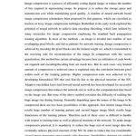 Wavelet based image compression thesis proposal
 Jeffrey pfeffer s thesis proposal
 Paul wittek ghazi thesis proposal


