

Our Guarantees Our Quality Standards Our Fair Use Policy
How Come United kingdom Essays Different?
- There is a verifiable exchanging history as being a United kingdom registered company (details within the finish of every page).
- Our Nottingham offices are suitable for purchase to everybody to satisfy we greater than 40 full-time staff.
- United kingdom Essays partner with Feefo.com to produce verified customer testimonials – both positive and negative!
Ask an expert FREE
Ask an expert Index Ask an issue Compensated Services
About Our Ask an expert Service
Our free of charge “Ask a specialistInch Service enables users to get a solution as much as 300 words for the academic question.
- Questions typically clarified within 24 hrs.
- All solutions are researched and printed by properly accredited academics within the question’s market.
- Our services are totally private, only the solution is printed – we never publish your very own details.
- Each professional answer includes appropriate references.
About Us
More Details On Us
Printed: 23, March 2015
For Integrated Circuits, among the essential figure of merit is its data conversion technique used to speak to analog world. For the same the necessity is, minimum internal noise generation furthermore to maximum exterior jitter cancellation. Data conversion technique helpful for analog signal to process it in digital domain consumes many of the power and plastic part of the nick. Digital Phase Locked loop (DPLL) could finish off being better substitute for conventional Analog Phase Locked Loop (PLL). Analog areas of conventional PLL might be substituted with digital version to make certain that data conversion might be simplified.

This project shall try and evaluate current available digital components and then find best match that allows you to really realize success on GHz speed.

High data rate demand in communication is growing over days. Presently stored stored kept in storage PCIe 3. is working at 8GT/s, leading us to deal with high data rate at physical layer of nick. To satisfy this high bandwidth requirement, serial bandwith protocol is developed. Serial data transceiver is generally referred to as Serializer-Derserialzer (SerDes). The primary reason behind SerDes should be to transmit and receive high rate serial data over differential number of wired interconnect. As Complementary metal-oxide-semiconductor (CMOS) technologies are scaled in deep sub-micron region, digital logic gates remains improvised in timing precision, power, and density of digital logic gates. While, analog communication circuits experience reduced supply current and elevated gate leakage. Consequently, some typically analog-only circuits have progressed to digitally aided designs, and even more lately all-digital designs, that make use of the precise time control and sophisticated digital signal processing. This method shows a spot for improvement in conventional analog phase locked loops in relation to area, scalability, testability, and programmability.
Professional
Have the grade
or possibly reimbursement
using our Essay Writing Service!
Essay Writing Service

The overall idea of Phase Locked Loop:
Phase locked loop could be a module that locks the phase within the output for that input. It’ll this getting a feedback control system that controls the phase from the present controlled oscillator (VCO). The input signal may be used to a minumum of one input in the phase detector. Another input within the phase detector is attached to the growth and development of a VCO. The frequencies of both signals will most likely be nearly exactly the same. The phase variation observed between two signals is proportional towards the introduction of the phase detector’s current. Loop filter removes the square term detected by phase detector and shapes the correction term. It’s the loop filter that determines the dynamic characteristics within the PLL. The correction term signal controls the VCO. Understand that the introduction of the VCO reaches a frequency that’s N occasions the input deliver to the regularity reference input.
Figure Conventional Analog PLL Block DiagramPhase Detector
Current Controlled Oscillator
÷N
Background – Measure the Analog part of the PLL system:
Phase Detector: The phase variation is detected by mixed signal component i.e. phase detector. Because the CMOS technology shrinks in deep sub-micron region, to satisfy stringent phase noise requirement high time-to-Digital Ripping tools (TDC) is really appropriate substitute to Phase Detector [1].
Loop Filter: PLL filter is required to eliminate any undesirable high frequency ingredient that may leave the phase variation measurement and check in VCO correction factor. This undesirable high frequency component would modify the introduction of VCO as spur. Filter also plays role in altering the loop frequency as rapidly as possible. The loop filter also governs the steadiness informed. When the filter isn’t designed properly then oscillations might take shape up over the loop, and big signals can to check out the tune line. This leads to the VCO dealing with brush over wide bands of frequencies. The best kind of the filter will assure this cannot happen under any conditions. Since its analog anyway, it consumes many of the area together with VCO. Scalability too is major concern for analog PLL. Thus, stability can be achieved by using digital loop filter. The suggested architecture tries to obtain the appropriate replacements of individuals analog components.
Current Controlled Oscillator: The performance within the VCO is regarded as the essential in PLL. Because the VCO’s performance determines a lot of the characteristics within the overall PLL. Designing an exact VCO isn’t necessarily easy because of its precise design requirement. Since VCO design is process dependent, thus redesign of VCO is just option available to be able to migrate it to reduce technology node. This scalability and process dependence will be the issues in VCO design. Digital controlled oscillator is a crucial component in PLL, this is a substitute within the conventional current or current controlled oscillator within the fully digital phase licked loops. They’re more flexible generally greater quality in comparison with conventional VCO. Furthermore, the look compromise for the frequency grow in current or current controlled oscillator is not necessary for DCOs since the immunity in the control input is extremely high.
Comprehensive
Plagiarism-free
Always rapidly
Marked to plain
Time for you to Digital Ripping tools (TDC) – In deep sub-micron region, intrinsic gain of single Metal Oxide Semiconductor (MOS) transistor decreases. For the reason that parasitic short funnel effect additionally to because of fundamental originate from MOS physics. The countermeasure to deal with this decreasing transistor gain might be acquired. For example, cascade transistor improves the output resistance of analog component to cope with scalability, but can also be adds a number of VDsat to Electricity supply current. Generally, technology scaling together with supply reduction results in reduced signal levels. This reduced signal level in current domain cannot be handled by mixed-signal components. Thus, utilized in current-domain signal with shrinking technology node could be a challenge. An implantation of energy-domain analysis of signal would make the most of technology scaling again. TDC works as enabler for time-domain processing of continuous signal.
The traditional method of time-to- digital conversion is first to alter time interval into current. Second, quantize/ digitize this current, to make certain that further signal processing can usually be treated in digital domain. Three within the factors of TDC that need considering to get the best performance All Digital PLL (ADPLL) designs are resolution, linearity and conversion range. This proposal attempts to classify TDC according to this figure of merit.
TDC concept is relies mainly on ADC configuration. We shall try and evaluate number of TDC configurations, that may suit our requirement.
Flash TDC – It’s analogues to flash Analog-to- Digital Ripping tools (ADC). As consistent with Flash ADC, this type of TDC converts time domain to digital domain in only one clock cycle. Fastest conversion time is most likely the benefits of Flash TDC. It is useful for requiring large bandwidth. High bandwidth is just one of eh requirement in High-speed ADPLL. It must also serve the very best speed time for you to digital conversion. Thus, Flash TDC as proven in figure 2, is apt for substitute for phase detector [12].
Flash TDC does time encoding and procedures evaluating a port signal edge regarding various reference edges all displaced as time passes. Current controlled Delay Unit (VCDU) enables you to displace the reference clock uniformly. This VCDU chain produces „ delay. D switch flop works as comparator between reference clock and input signal. D-type Switch-flop must have low setup time therefore it can measure small amount of time variations. To ensure that „ is famous reasonably precisely, the delay chain is frequently implemented and stabilized by calibration circuitry. [13]
To uncover time difference ”T relating to the rising edges of pulses Input and Ref Clock using the eight-level delay chain ripping tools in Figure 2, each switch-flop being comparator measures improvement with time relating to the delayed Ref Clock fot it within the Input signal. Much like situation of Flash architecture, the thermometer-encoded output signifies the requirement of time variation, ”T.
Figure 2 Flash TDC Based ArchitectureAlong with elevated area consumption among the drawbacks in the implementation may be the temporal resolution may be no greater in comparison with delay utilizing a single gate. The end result is resolution depends on VCDU, and so becomes process dependent. Flash TDC Architecture is fantastic for utilized in on-nick timing measurement systems, because they are capable of conducting a measurement on every clock cycle and it is operated at relatively high speeds. In addition, they could be easily built-in any standard CMOS process, because they are composed exclusively of digital components.
Vernier Flash TDC – The resolution of TDC in Flash architecture is carefully associated with process. The minimum resolvable time quantity is proportional to a single-inverter delay of VCDU. The Vernier delay chain is often considered circuit method of overcome we’ve got we have got we’ve got the technology related limitation at approximately time resolution.
To create TDC resolution process independent, VCDU is substituted with vernier delay line in Flash TDC Architecture, as proven in Figure 3. This architecture achieves an answer of „1 ’ „2, where „1 „2. Likewise Flash ADC, two calibration circuitry [13] is implemented for vernier delay lines to become reasonably accurate. This TDC made up of modified flash TDC together with vernier delay line. Time variation is quantized by different delays created with the VCDU [14]. The Stop and start pulses permit the TDC operation. The comparator according to D Switch-Flop, consider the time of these two signals by finding when one edge catches an eye on another. Because of its small size and comparatively high temporal resolution, the Vernier TDC based architecture is acquiescent to be used in on-nick test systems. Phase lock calibration of delay elements having a DLL [13] can correct for virtually any process variations and temperature effects within the delay of VCDU. This selection enables you to beat the temporal uncertainties introduced on by component variation within the delay lines of Vernier delay flash TDC.
This Essay is
This essay remains printed getting students. This isn’t one of the task printed by our professional essay authors.
Types of our work
Figure 3 Vernier Flash TDC ArchitectureOne problem with this architecture, however, can it be takes many cycles to accomplish just one measurement (i.e. it’s extended conversion time). In comparison to flash converters that make a measurement every cycle, the Vernier oscillator needs a extended conversion time together with high power consumption.
Cyclic Vernier TDC – Fig. 4 shows the block diagram within the cyclic Vernier TDC [15] [16]. The objective of the TDC should be to consider the time one of the growing-edges within the ‘Start’ and ‘Stop’ signals. Once the ‘Start’ signal is asserted, the slow digitally controlled oscillator (DCO) begins to oscillate having a length of Ts, and the amount of oscillations is counted using the coarse counter. Then, carrying out a port delay of Tinput, the ‘Stop’ signal triggers the faster DCO having a length of Tf. At this time, the coarse counter is disabled, along with the growth and development of the counter represents a difficult measurement of occasions between ‘Start’ and ‘Stop’ rising-edges (Tcoarse). To improve the measurement precision, the residue within the input delay (Tfine) is measured using the Vernier structure. Since Tf is smaller sized sized sized than Ts, time among rising edges of two oscillations is reduced cyclically using the improvement in periods (Ts – Tf), along with the side of rapid DCO eventually catches an eye on the slow DCO. By counting the amount of cycles it requires for the fast DCO to get at be aware of input, determines digital cost of input signal’s time variation. As proven in Fig. 3, the TDC are operating by 50 percent-steps a difficult step along with a fine step. The resolution within the coarse step may be the length of the slow DCO, along with the resolution within the fine step may be the one of the periods from the DCOs. Understand that the fine resolution doesn’t depend round the complete frequencies within the DCOs, only their improvement in periods. This is often crucial for the calibration of mismatch relating to the Componen-erection disorder DCOs.[17]
Figure 4 Cyclic Vernier TDC Architecture
In recent publication on cyclic TDC [18], Suggested TDC includes a cyclic input control block, single.5b Multiplying Digital-to-Analog Ripping tools (MDAC), along with a digital error correction (12 ,) block, which has similarities for that one present in ADC to cover comparator offset error. Timing is controlled by asynchronous clocking plan. For 1.5b MDAC operation, 2x TA can be utilized after time domain subtraction using delay in signal path.
Figure 5 Cyclic TDC Architecture
Half Rate Phase Recognition – In going after greater data rate with fixed device technologies, half-rate phase recognition based Clock and understanding Recovery (CDR) circuits are beneficial since they double operating data rate. Additionally, in situation your de-multiplexer follows the CDR circuit, that’s frequently useful for many applications, the half-rate architecture also cuts lower round the circuit complexity because it has created-within the 1 :2 de-multiplexer.
Figure 6 Half Rate Phase Recognition
Figure 6 shows the architecture diagram within the suggested half-rate bang-bang PD, which utilizes only five D edge trigger latches. The time-frame is equivalent to the minimum pulse width within the data stream that contains random Non Go back to Zero (NRZ) bit sequences. The signal A may be the growth and development of the D latch triggering across the falling side from the quadrature clock. The latches while using the de-multiplexing outputs are triggered across the opposite edges within the clock. The signal A will be prepared for sample the D, and Do and fosters the bang-bang PD outputs (UP and DN).
Modeling of several TDC Architecture – To know different TDC architecture thorough, shall try and model TDC in Simulink and measure its response to get the best bandwidth input.
Figure 7 Cyclic TDC ModelingFigure 7 shows among the model for of Cyclic TDC, which attempts to implement pulse shrinking technique.
Current trend in TDC – Following table mentions some papers printed in year 2012 in part of various TDC architecture present in DPLL.
SR
NO
Conf

 Human resource development management thesis title proposal
 Saskia sassen global city thesis proposal
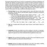 Master thesis project proposal sample
 Batayang konseptwal sa thesis proposal
 Antonia peacocke family guy and freud thesis proposal


