Presentation on theme: “Delay Locked Loop with Straight line Delay Element Goran Jovanovi, Mile Stojev and Dragia Krsti Faculty of Electronic Engineering, Ni, Serbia and Montenegro.”— Presentation transcript:
1 Delay Locked Loop with Straight line Delay Element Goran Jovanovi, Mile Stojev and Dragia Krsti Faculty of Electronic Engineering, Ni, Serbia and Montenegro TELSIKS 2005, Ni
2 DLL circuit is ideal for fine, precise, and accurate pulse delay control within the high-speed digital and mixed integrated circuits. Idea of DLL achieve correct synchronization between different digital blocks (CPU and SDRAM interface. ), eliminate clock skew and jitter within VLSI ICs, low-jitter clock synthesis, implementation of energy-to-Digital-Ripping tools with Vernier delay pattern, PN code tracking in spread spectrum systems… Applying DLL
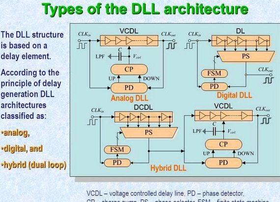
3 Kinds of the DLL architecture VCDL – current controlled delay line, PD – phase detector, Clubpenguin – charge pump, PS – phase selector, FSM – finite condition machine The DLL structure draws on a delay element. Using the principle of delay generation DLL architectures considered: analog, analog, digital, and digital, and hybrid (dual loop) hybrid (dual loop)
4 Classification of delay line elements Variable delay line elements are classified as: Digital- Controlled Delay Elements (DCDEs)Digital- Controlled Delay Elements (DCDEs) known as volume of delay areas of variable length (the amount of elements within the chain determines the quantity of the delay). Current-Controlled Delay Elements (VCDEs)Current-Controlled Delay Elements (VCDEs) are inverter-based circuits, efficient in applications where small, accurate, and precise amount of delay is essential to attain.
5 Typical to VCDLs Advantages: Simple structuresSimple structures Fine delay resolutionFine delay resolutionDisadvantages: Current controlled DLs have non-straight line transfer function, delay variation in term of control voltageVoltage controlled DLs have non-straight line transfer function, delay variation in term of control current Problem of VCDL realization was considered by: Y. Moon, et al. “An All-Analog Multiphase Delay-Locked Loop Having a Replica Delay Line for Wide-Range Operation and periodic-Jitter Performance”, IEEE JSSC, vol.35, No. 3, pp. 377-384, March 2000.Y. Moon, et al. “An All-Analog Multiphase Delay-Locked Loop Having a Replica Delay Line for Wide-Range Operation and periodic-Jitter Performance”, IEEE JSSC, vol.35, No. 3, pp. 377-384, March 2000. M. Maymandi-Nejad, M. Sachdev, “A digitally Programmable Delay Element: Design and Analysis”, IEEE Trans. on VLSI Systems, vol. 11, No. 5, October 2003.M. Maymandi-Nejad, M. Sachdev, “A digitally Programmable Delay Element: Design and Analysis”, IEEE Trans. on VLSI Systems, vol. 11, No. 5, October 2003. G. Jovanovi, M. Stojev, “Voltage Controlled Delay Line for Digital Signal”, Facta Universitatis, Series: Electronics and Energetic, vol. 16. No. 2, pp. 215-232, August 2003. G. Jovanovi, M. Stojev, “Voltage Controlled Delay Line for Digital Signal”, Facta Universitatis, Series: Electronics and Energetic, vol. 16.
No. 2, pp. 215-232, August 2003.
6 Everything you propose Linearization of VCDL’s transfer functionLinearization of VCDL’s transfer function We use Current Starved DE.We use Current Starved DE. Why:Why: –Simple structure –Relatively volume of delay regulation How you achieve straight line VCDL?How you achieve straight line VCDL? –We personalize the bias circuit. –We use a non-straight line bias circuit which draws on the square-law characteristics in the MOS transistor in saturation. –By a cascade connection of two non-straight line elements, the bias circuit along with the current starved delay element, there’s a straight line transfer function (delay in relation to control current).
7 Delay Line Element – standard solution Cascade composition in the bias circuit and VCDL where: t delay – delay time, C – parasitic output capacitance, V sw clock buffer (inverter) swing current, I clubpenguin – charging/discharging current of C.
10 Bias circuit HSpice simulation Charge-discharge current variation in relation to control current Relative approximation error within the reciprocal charge-discharge current variation in relation to control current
11 Current starved VCDL with straight line delay regulation – Complete design – Schematic of 4 stage DL
12 HSpice delay line simulation – results communicate with CLK out4 – Time delay, t delay, in term of control current V ctrl Relative approximation error of energy delay, t delay, in term of control current V ctrl
13 DLL differential architecture New DLL architecture with: differential charge pump, two low-pass filter and nonlinear bias circuit with differential input
16 Conclusion An implementation of DLL getting a vertical line VCDL is suggested. Current starved DL can be utilized. Linearization is achieved by modifying the bias circuit of current starved DL. HSpice simulation results points that for 1.2 m CMOS technology high delay linearity (error is less then 500 ps) inside the full-choice of regulation (from 28 to 55 ns) is achieved. Straight line DL demands new DLL architecture with differential charge pump, two low-pass filter and bias circuit with differential input.




 L intro d une dissertation proposal
 Loaning system for thesis proposal
 Rice leaf folder thesis proposal
 Abortion is wrong thesis proposal
 Entrepreneurs born or made dissertation proposal
