Contents
Introduction
A photocatalytic reaction proceeds in the existence of light–typically visible or Ultra violet–and catalyst–frequently a semi-conductive transition metal oxide for example titanium dioxide (TiO2 ). This experiment can give an intro into wastewater treatment via photocatalysis by calculating the degradation kinetics of methylene blue like a purpose of catalyst loading, peroxide concentration, and experimental setup.
Pre-Lab Questions
You are able to download the Pre-Lab questions with this experiment here.
Background
Take a look at textbook on chemical reaction engineering, particularly individuals chapters that go over experimental resolution of rate laws and regulations [1] and heterogeneous catalysis [2]. Most frequently, a pseudo first-order kinetic model is selected to find out rate laws and regulations within this experiment however, you should compare other models (specially the Langmuir-Hinshelwood model) too.
If you are unfamiliar with straight line and non-straight line regression then you need to review these topics too, either around the Statistics wiki (forthcoming) or perhaps in your textbooks. [3]
Theory
Photocatalysis is really a sizable field there are thousands of papers to see it’s suggested that you simply have a morning–and perhaps and mid-day–to do this. If you are reluctant or not able to see everything, we have categorized a couple of favorites below that will help you along.
Review Articles
This content give a good overview and context for that field but intentionally don’t have the specificity of research articles.
- Parameters affecting the photocatalytic degradation of dyes using TiO2 -based photocatalysts: An evaluation. [4]
- Photocatalytic degradation for ecological applications – an evaluation [5] (good coverage of ecological aspects).
- Titanium dioxide photocatalysis [6] (good physical chemistry aspects).
- Heterogeneous photocatalytic degradation of organic contaminants over titanium dioxide: Overview of fundamentals, progress, and problems. [7]
- Tailored titanium dioxide photocatalysts for that degradation of organic dyes in wastewater treatment: An evaluation [8] (an extensive review including much nano-TiO2 ).
- Management of hazardous organic and inorganc compounds through aqueous-phase photocatalysis: An evaluation. [9]
- Photophysical, photochemical and photocatalytic facets of metal nanoparticles (good review from the quality journal). [10]
- Photocatalysis on TiO2 surfaces: Concepts, mechanisms, and selected results [11] (classic review with more than a 1000 citations. You’ll find the very structure of numerous titanium oxides here).
Research Articles: Slurry Reactors
This content were selected for his or her analysis of dye degradation in slurry reactors. Observe that nanometer-sized TiO2 particles are utilized very differently in the micron-sized particles we use within the lab, which only a small amount of studies use these questions slurry once we do. We discovered that nanometer-sized particles were an undesirable option for a teaching lab because of safety concerns.
- Photocatalytic degradation path of methylene blue in water. [12]
- TiO2 -aided photocatalytic degradation of azo dyes in aqueous solution: kinetic and mechanistic investigations. [13]
- Photocatalytic degradation of various dyes in water by Ultra violet-irradiated titania. [14]
- Kinetics of photocatalytic degradation of reactive dyes inside a TiO2 slurry reactor. [15]
- Photocatalytic degradation of numerous dyes by combustion synthesized nano anatase TiO2. [16]
- Variation of Langmuir absorption constant determined for TiO2 -photocatalyzed degradation of acetophenone under different light intensity. [17]
- Adsorption of methylene blue and acidity blue 40 on titania from aqueous solution. [18]
- Photodestruction and COD elimination of toxic dye erioglaucine by TiO2 -Ultra violet process: influence of operation parameters. [19]
- An over-all treatment and classification from the solute absorption isotherm. [20]
Research Articles: H2 O2 /TiO2 Systems
This content were selected for his or her utilization of H2 O2 and TiO2 for dye degradation.
Observe that many are designed in a way much like our lab reports but from time to time employ poor writing styles.
- Photocatalytic degradation of disperse blue 1 using Ultra violet/TiO2 /H2 O2 process. [21] Observe that this isn’t an excellent journal, the writing is not exceptional, and also the H2 O2 concentration never was mentioned. The mechanism is nice when compared to next two references but nonetheless not complete look within the previous references for that full mechanism.
- Management of Remazol brilliant blue dye effluent by advanced photo oxidation process in TiO2 /Ultra violet and H2 O2 /Ultra violet reactors. [22]
- H2 O2 /TiO2 photocatalytic oxidation of metol. Identification of intermediates and reaction pathways. [23]
Standard Operating Procedure
Safety
- Lab jackets and protective eyewear ought to be worn whatsoever occasions.
- Get rid of damaged glasses within the appropriately labeled receptacles used filters could be discarded within the trash.
- Don’t get rid of waste to waste! Make use of a flask to gather all waste then inform the TA or instructor in the finish from the lab period.
- Methylene blue is really a potent textile dye. When connecting tubing or transferring liquid, be careful to not splash.
- Relevant chemical information continues to be indexed by Table 1.
Table 1. Chemicals as well as their formulas, hazards, and suppliers for Ultra violet photocatalysis.
Preparation
- Understand the Ultra violet/VIS spectrophotometer and also the data acquisition software. Note there are two kinds of measurements:
- Absorption spectrum. Make use of this to look for the wave length of maximum absorbance.
- Point measurement. Make use of this to determine absorbance in a single, pre-set wave length.
- Produce a calibration curve.
- Prepare about 100 mL of the solution of known dye concentration typically 10 parts per million is enough.
- Get the absorption spectrum of the solution. If you notice a plateau rather of peaks then your option would be too concentrated and must be diluted.
- Note the wave length of maximum absorbance, (lambda_>).
- Measure absorbance at (lambda_>) for many diluted solutions, including deionized (DI) water. Minimize waste by utilizing measurement pipets, plastic cuvettes along with a serial dilution procedure.
- Measure the level of the reactor-flask system.
- Pick a small or medium-sized glass spinner flask.
- Put the flask around the stir plate and fasten the pump lines.
- Fill the flask with sufficient DI water to submerge the right pump line.
- Run the peristaltic pump until continuous circulation is achieved between your flask and Ultra violet reactor. adding water as essential to keep your appropriate pump line submerged. Flow with the Ultra violet reactor ought to be from bottom to top.
- The entire amount of water utilized in Steps 3 and 5 is the level of water you need to use to organize solutions for subsequent runs.
- Drain the machine. Make use of a large glass spinner flask or any other appropriate glass flask to keep your waste. Don’t dump waste to waste.
Fundamental Operation
- Within the spinner flask, prepare a suitable amount of solution of known (measured) dye concentration (
10 parts per million) with TiO2 (
1000 parts per million) in DI water. Make use of the stir plate to interrupt up clumps of TiO2. Please be aware – there’s you don’t need to prepare these solutions individually, both TiO2 and dye can be included to the answer simultaneously.
- Absorbance measurements are meaningless unless of course the sample is sufficiently filtered.
- Don’t filter the samples near the face! It’s not hard to rupture the syringe filter or connections throughout the filtration process should you go too quickly.
- About 20 mL of solution could be filtered prior to the filter ought to be replaced.
Shutdown
- Switch off the Ultra violet reactor.
- Drain the Ultra violet reactor and consolidate waste right into a single, large spinner flask.
- If more waste was created than can fit in one flask, then fill just one flask and put excess waste in another glass container the second don’t have to be a spinner flask.
- Add about 5 mL H2 O2. then switch on pump, stirrer, and Ultra violet reactor.
- Before leaving the lab, inform the TA or Instructor which flasks are waste.
Common Report Mistakes and Suggestions
The evaluator(s) with this experiment was requested to list out 3 or more common errors frequently made around the reports with this experiment, in order to provide 3 or more suggestions that may improve the caliber of reports with this experiment. The responses were the following:
- small font size within the figures
- incomplete citations
References
- Fogler, H. Essentials of Chemical Reaction Engineering. Prentice Hall: Boston, 2011 Ch. 7.
- ibid, Ch. 10.
- Fogler, H. Essentials of Chemical Reaction Engineering Pearson Education: Boston, 2011, Ch. 7.
- Akpan, U.G. Hameed, B.H. J. Hazard. Mater.,2009,170. 520-529.
- Bhatkhande, D.S. Pangarka, V.G. Beenackers, A. J. Chem. Technol. Biotechnol.,2001,77. 102-116.
- Fujishima, A. Rao, A.N. Tryk, D.A. J. Photochem. Photobiol C: Photochem. Reviews,2000,1. 1-21.
- Gaya, U.I. Abdullah, A.H. J. Photochem. Photobiol. C: Photochem. Reviews,2008,9. 1-12.
- Han, F. Kambala, V. Srinivasan, M. Rajarathnma, D. Naidu, R. Appl. Cat. A: General,2009,359. 25-40.
- Kabra, K. Chaudhary, R. Sawhney, R.L. Ind. Eng. Chem. Res.,2004,43. 7683-7696.
- Kamat, P.V. J. Phys. Chem. B,2002,106. 7729-7744.
- Linsebigler, A.L. Lu, G. Yates Junior. J.T. Chem. Rev.,1995,95. 735-758.
- Houas, A. Lachheb, H. Ksibi, M. Elaloui, E. Guillard, C. Herrmann, J.M. Appl. Catal. B: Environ.,2001,31. 145-157.
- Konstantinou, I.K. Albanis, T.A. Appl. Catal. B: Environ.,2004,49. 1-14.
- Lachheb, H. Puzenat, E. Houas, H. Ksibi, K. Elaloui, E. Guillard, C. Herrmann, J.M. Appl. Catal. B: Environ.,2002,39. 75-90.
- Sauer, T. Cesconeto Neto, G. Jose, H.J. Moreira, R.F.P.M. J. Photochem. Photobiol. A: Chem.,2002,149. 147-154.
- Sivalingam, G. Nagaveni, K. Hegde, M.S. Madras, G. Appl. Catal. B: Environ.,2003,45. 23-38.
- Xu, Y. Langford, C.H. J. Photochem. A: Chem.,2000,133. 67-71.
- Fetterolf, M.L. Patel, H.V. Jennings, J.M. J. Chem. Eng.,2003,48. 831-835.
- Jain, R. Sikarwar, S. Int. J. Phys. Sci.,2008,3. 299-305.
- Giles, C.H. D’Silva, A.P. Easton, I.A. J. Coll. Intf. Sci.,1973,47. 766-778.
- Saquiba, M. Abu Tariqa, M. Haquea, M.M. Muneer, M. J. Environ. Mgmt.2008,88. 300-306.
- Verma, M. Ghaly, A.E. Am. J. Eng. Appl. Sci.,2008,1. 230-240.
- Aceituno, M. Stalikas, C.D. Lunar, L. Rubio, S. Perez-Bendito, D. Water. Res.,2002,36. 3582-3592.
TiO2 is really a generally known semiconductor with photocatalytic activities which are attracting extensive interest due to its special optoelectronic and physiochemical qualities [ 1 ]. It might potentially be utilized in a variety of applications, including wastewater treatment, air purification, disinfection, and surface self-cleaning [ 2. 3 ]. However, its low utilization ability of visible light and secondary pollution have limited its applications in certain areas. Briefly, the bandgap width of anatase TiO2 is 3.2 eV, and it is excitation wave length is 387 nm. Thus, only negligence ultraviolet (Ultra violet) light with wave length 387 nm can excite the photocatalytic activity of TiO2. while, 90% of visible light can’t be utilized [ 4. 5. 6 ]. However, the separation from the fine TiO2 powder from solution after degradation is challenging and pricey [ 7. 8. 9 ]. Considerable efforts happen to be dedicated to preparing visible-light-active TiO2 materials and support materials with bigger adsorption capacities to be able to utilize TiO2 better.
To improve the visible light absorption of TiO2 materials, transition metals were added into TiO2 to enhance its photocatalytic activity by reduction of the power bandgap width or stopping (e − /h*) pair recombination through electron/hole trapping [ 10. 11. 12. 13. 14. 15. 16. 17. 18 ]. However, it had been well-known the transition metals doped TiO2 endured in the poor stability for that lengthy-term operation. More lately, many studies have concentrated on preparing N-doped TiO2 powders and flicks via various synthesis routes [ 19. 20 ]. It had been demonstrated that whenever N atom was doped in to the TiO2 anatase lattice a donor condition was created just over the valence band, which boosts its visible light absorbance. Other researchers discovered that transition metals/N co-doped into TiO2 would facilitate the introduction of photocatalysts [ 21. 22. 23 ]. Additionally, activated carbon fibers (ACFs) showing good adsorption and uniform pore structure happen to be utilized as catalyst supports for TiO2 loading. However, ACFs, as the ideal choice of supporting material, mostly are prepared from fossil sources [ 24. 25 ], that are considered to possess a negative effect when it comes to sustainability. We has formerly reported producing ACFs from renewable sources (woodsy biomass) (WACF) as support for TiO2 loading [ 26. 27 ].
In our work, WACF composite packed with Mn/N-co-doped TiO2 (Mn/Ti-N-WACF) was made by sol–gel and impregnation method. The influences of Mn doping contents around the structure, surface groups, and visual light absorption of Mn/Ti-N-WACF were investigated using checking electron microscopy, X-ray photoelectron spectroscopy, and ultraviolet–visible (Ultra violet-vis) spectrophotometer, correspondingly. Additionally, the photocatalytic degradation behavior of methylene blue (MB) was utilized to judge the photoactivities from the prepared samples.
2. Experimental Section 2.1. Samples
A number of Mn/N co-doped TiO2 with various Mn doping contents was prepared using sol–gel method. Inside a typical procedure, .03 mol of tetrabutyl orthotitanate (C16 H36 O4 Ti, Damao Chemical Reagent Factory, Tianjin, China) was dissolved in 60 mL of ethanol, some MnSO4 solution ended up being added with molar ratio of Mn:Ti from to twoPercent. The answer was stirred for 30 min until it grew to become completely transparent. Meanwhile, 2 mL of acetic acidity was put into 60 mL of ethanol and a pair of.2 mL from the sterilized water to from another solution. The second solution and .3 g of urea were gradually put into the previous one under energetic stirring until completely dissolved. Finally, the mixed solution was put into a thermostatic water bath at 40 ଌ for just two h for aging to acquire a milky white-colored colloidal solution composed of Mn/N co-doped TiO2 sol.
Formerly characterised WACF samples [ 28 ] were added in to the above solution and mixed by vibration for 30 min. Following a certain duration of still dipping, the fibers were dried at 105 ଌ for just two h, adopted through the calcination at 450 ଌ for 1.5 h within dry air flow after which cooled to 70 degrees. The load from the Mn/Ti-N-WACF photocatalytic material was recorded. The samples prepared from various Mn:Ti molar ratios: :1, 1:600, 1:300, 1:100, and 1:50, that have been denoted as Ti-WACF, Mn/600Ti-N-WACF, Mn/300Ti-N-WACF, Mn/100Ti-N-WACF, Mn/50Ti-N-WACF, correspondingly.
The top morphology from the photocatalysts was observed utilizing a FEI NANOSEM 430 checking electron microscope (SEM, FEI, Hillsboro, OR, America) with thermal field emission.
The XRD diffractograms were acquired utilizing a Rigaku D/max2500 powder X-ray diffractometer (Rigaku, Tokyo, japan, Japan) installed with Cu Kα ray (λ = 1.5405 Å) and operated in the tube current of 40 kV, tube current of 100 mA, within the checking position (2θ) varying from 20 to 80°, and checking speed of 8° min 𢄡. The typical diameter D (nm) from the photocatalysts were calculated using Scherrer formula D = .89λ/(㬬osθ), where λ may be the X-ray wave length (.154 nm), θ may be the Bragg position of diffraction peaks (°) and β is full width at half maximum (FWHM). The FWHM of every diffraction line was resolute in the profile measured having a checking rate of just oneOr2° (2θ) min 𢄡. that was calibrated by standard plastic powder for instrumental broadening.
XPS measurements were transported on a Kratos Axis UltraDLD multi-technique X-ray photoelectron spectroscopy (Shimadzu, Kyoto, Japan) having a monochromated Al Kα X-ray source (hν = 1486.6 eV). XPS survey spectra were recorded with pass energy of 80 eV, and resolution spectra with pass energy of 40 eV. For calibration purposes, the C 1s electron binding energy akin to graphitic carbon was set at 284.6 eV. Atomic ratios were calculated in the XPS spectra after correcting the relative peak areas by sensitivity factors based on the transmission characteristics from the Physical Electronics SCA. A nonlinear least squares curve-fitting program (XPSPEAK software, Version 4.1) was utilized for XPS spectral deconvolution.
A Ultra violet-3600 spectrophotometer (Shimadzu, Kyoto, Japan) was utilized to characterize the Ultra violet-vis absorbance from the samples. The diffuse reflectance spectra from the samples over a variety of 200� nm were recorded at 70 degrees in air from 200 to 700 nm.
The degradation from the model dyes (MB) was performed inside a 200 mL reactor. A 65 W tungsten halogen lamp having a 400 nm cutoff filter was utilized as visible source of light. The space between your strip lamp and fluid level was stored at 15 cm. The first power of the MB solution was 33 mg/L. Ten milligrams Mn/Ti-N-WACF and 100 mL from the MB aqueous solution were added in to the reaction system. Before illumination, the suspension was magnetically stirred for 40 min at nighttime to make sure that the mix arrived at towards the adsorption equilibrium. Throughout the photoreaction process, 3 mL from the solution was collected periodically. The photocatalyst was separated in the solution by centrifugation, and also the power of the rest of the obvious liquid was resolute using Ultra violet-vis spectroscopy.
3. Results and Discussion 3.1. SEM Analysis
Figure 1 shows the SEM pictures of WACF and Mn/Ti-N-WACF. In contrast to the initial WACF ( Figure 1 a,b), the top of Mn/Ti-N-WACF was engrossed in a uniform layer of Mn/N-co-doped nano-TiO2 film ( Figure 1 c–h). The Mn/N-co-doped nano-TiO2 was effectively loaded around the WACF surfaces whereas the perimeters tilted in certain regions, although some films taken off in the WACF support. This can be related to the contraction from the base material and movie during calcination. Mn/N-co-doped nano-TiO2 demonstrated mild agglomeration around the fiber surface. However, the agglomeration degree was under those of the Mn/N-co-doped nano-TiO2 powder. This finding signifies that a number of pores around the WACF surface might help avoid the agglomeration from the nano-TiO2 particles throughout the loading process. However, certain parts of WACF base material weren’t covered completely after loading. Abundant pores around the non-loaded WACF surfaces might be favored for that subsequent Ultra violet-vis adsorption and photocatalytic functions.
SEM pictures of activated carbon fibers from woodsy biomass (WACF) before ( a and b ) after ( c – h ) loading of Mn/N-co-doped TiO2. The inset micrographs ( b. d. f. and h ) were enlarged images.
3.2. XRD Analysis
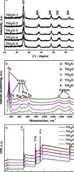
The XRD patterns of activated carbon fibre packed with Mn/N-co-doped TiO2 after calcination at 450 ଌ are proven in Figure 2. All diffraction peaks of (101), (004), (200), (105), (211), (204), (220), and (215) match the characteristic peaks of anatase TiO2 [ 29. 30. 31 ]. No diffraction peaks of rutile and brookite put together. This result established that under calcination at 450 ଌ, the Mn/N co-doping and loading around the activated carbon fibre didn’t modify the very phase of nano-TiO2. Because the Mn doping content elevated, the height of (101) for that co-doped samples shifted for the left in contrast to pure TiO2. The diffraction position was decreased, and also the interplanar spacing was elevated. This phenomenon is led to the Mn/N doping within the TiO2 lattice enhanced through the distortion from the octahedron in tetragonal anatase TiO2. Because the Mn doping content elevated, the concentration of the height was decreased after which elevated. Just the sample Mn/50Ti-N-WACF demonstrated greater concentration of peak (101) compared to pure TiO2. This result established that Mn/N co-doping reduced the crystallization amount of TiO2 when Mn/Ti ratio was 1/50. No impurity peaks associated with Mn and N were based in the XRD patterns because of the low doping content.
X-ray diffraction (XRD) patterns akin to different Mn doping contents.
Table 1 shows the mean grain diameters from the Mn/N-co-doped TiO2 within the composite calculated while using Scherrer equation and also the parameters from the peak (101). The mean grain diameters were within 23� nm, which ranges within the nano scale. All grain diameters from the Mn/N-co-doped TiO2 were smaller sized compared to pure TiO2. This established that Mn/N co-doping could effectively avoid the nano TiO2 agglomeration throughout the calcination process. Because the Mn doping content elevated, the grain diameter within the composite was reduced to 26.6 nm for Mn/100Ti-N-WACF when compared with pure TiO2 (36.4 nm), after which elevated to 36.2 nm for sample Mn/50Ti-N-WACF. More than Mn doping would make the agglomeration of nano TiO2 particles.
polymers-07-01476-t001_Table 1 Table 1
Mean grain diameters of Mn/N-co-doped nano-TiO2 in composites.
3.3. XPS Analysis
To acquire details about caffeine composition from the fiber surface and also the binding characteristics from the elements in the surface, XPS measurements were transported out. The broad scan XPS spectra outcomes of all samples were proven in Table 2. The plethora of 100� eV binding powers incorporated the peaks of C 1s, O 1s, Ti 2p, Mn 2p, N 1s, and P 2p. This recommended the samples were made up of the weather C, O, and Ti, in addition to a little bit of Mn, N, and P. P was originated in the phosphoric acidity added during phosphoric acidity activation to organize the liquefied wood. C (atom %) and O (atom %) were the dominant components, as the N content didn’t show any significant variation of all the composites samples but demonstrated a contrary trend in contrast to the O content. The Ti content of Mn/Ti-N-WACF was greater compared to Ti-WACF. It was related towards the greater loading efficiency of Mn/N-co-doped TiO2 around the porous surfaces of activated carbon fibers. The Ti content decreased because the Mn doping amount was elevated. This phenomenon was most likely brought on by the substitution from the Ti ions by Mn ions within the TiO2 lattice. Furthermore, of all the co-doped samples Mn/300Ti-N-WACF had the greatest O/C ratio.
polymers-07-01476-t002_Table 2 Table 2
Global surface composition determined using X-ray photoelectron spectroscopies (XPS).
Figure 3 shows our prime-resolution XPS patterns from the Ti 2p orbital from the samples. The figure implies that the Ti 2p had two different orbitals, including Ti 2p1/2 (464.5 eV) and Ti 2p3/2 (458.8 eV). The power interval backward and forward peaks was 5.7 eV, indicating that Ti existed by means of Ti 4+ within the samples [ 32 ]. Because the Mn doping content elevated, the Ti 2p3/2 binding energy shifted for the lower energy and hybridization, which recommended the electron density from the chemical atmosphere surrounding Ti was elevated because of partial O atoms was substituted with a couple of N atoms within the TiO2 lattice.
For that N 1s orbital with growing Mn doping content, the N 1s peaks of Mn/Ti-N-WACF made an appearance at 400.1, 399.7, 399.4, and 399.9 eV, for that examples of Mn/600Ti-N-WACF, Mn/300Ti-N-WACF, Mn/100Ti-N-WACF, and Mn/50Ti-N-WACF, correspondingly. To be observed that the plethora of 397.5 to 400.3 eV was akin to Ti–N–O. Following the peak splitting of N 1s ( Figure 4 ), the peaks also made an appearance within the parts of �.5 eV (N–Ti–N) and � eV ascribing to NO x [ 33. 34 ]. This confirmed that N from the Mn/Ti-N-WACF samples substituted a few of the O atoms within the TiO2 lattice.
High-resolution Ti 2p XPS spectra of samples.
XPS spectra of numerous samples in the N 1s region.
Our prime-resolution C 1s spectra from the samples are proven in Figure 5. Deconvolution from the XPS C 1s spectra revealed five individual peaks that represent the next: graphitic carbon (Cp1. 284.6 eV) carbons contained in phenol, alcohol, ether, or C=N groups (Cp2. 285.7�.9 eV) carbonyl or quinine groups (Cp3. 286.4�. eV) carboxyl, lactone, or ester groups (Cp4. 288.5�.9 eV) and carbonate groups (Cp5. 289.5�.8 eV) [ 35 ]. The percentages of carbon atoms from graphite or from various functional groups were calculated ( Table 3 ). The intensity (mass %) of both graphitic carbon (Cp1 ) and carbons (Cp2 𠄼p5 ) within the oxygen-that contains groups demonstrated significant variations between Ti-WACF and Mn/Ti-N-WACF. The Cp1 items in all Mn/Ti-N-WACF samples were lower compared to Ti-WACF. In comparison, the Cp3 items in all Mn/Ti-N-WACF samples were greater compared to Ti-WACF. The released O in the TiO2 colloids and also the little bit of O substituted by N within the co-doped samples were absorbed through the pores present within activated carbon fibre during high-temperature calcination. Thus, the end result established that Mn/N co-doping not just influenced the TiO2 lattice, but additionally not directly affected the lattice composition of WACF. In contrast to Ti-WACF, the Mn/N-co-doped samples contained Cp5. indicating the co-doped samples had greater reactivity than Ti-WACF.
High-resolution fitted C 1s spectra of samples.
polymers-07-01476-t003_Table 3 Table 3
Outcomes of fits from the C 1s regions. Values given as % of total intensity.
Peak fitting of O 1s region of XPS spectra was conducted ( Figure 6 ). Three individual peaks made an appearance at 530, 532, and 533.3 eV, were allotted to OL (lattice oxygen), OOH (hydroxyl oxygen), and Oad (adsorbed oxygen), correspondingly [ 36. 37 ]. Quantified area percentages of every peak are proven in Table 4. Because the Mn doping content elevated, The OL items in the Mn/Ti-N-WACF samples first of all elevated and decreased. In comparison, the OOH contents first of all decreased and elevated. The Oad items in the co-doped samples elevated using the Mn doping content growing. Meanwhile, it had been also acquired at 536 eV akin to the Ti–O–N bonds in Mn/Ti-N-WACF samples [ 28 ]. These bits of information were most likely brought on by the response from the doped N with Oad developing NO x throughout the high-temperature (450 ଌ) calcination process. Furthermore, the OL content of Mn/300Ti-N-WACF was considerably greater compared to another samples, indicating this sample had good redox ability ( i.e. strong photocatalytic activity).
High-resolution fitted O 1s spectra of samples.
polymers-07-01476-t004_Table 4 Table 4
Outcomes of fits from the O 1s regions. Values given as % of total intensity.
3.4. Ultra violet-vis Spectrometry
The Ultra violet-vis diffuse reflectance spectroscopy of Ti-WACF and Mn/Ti-N-WACF samples were proven in Figure 7. In contrast to Ti-WACF, the absorption fringe of the Mn/Ti-N-WACF samples now use the visible light region upon doping because of the little bit of Mn that injected in to the TiO2 lattice or existed within the gap of TiO2. It had been further shown the Mn doping could narrow this guitar rock band gap of TiO2 and extend the absorption selection of TiO2 to visible light region. Furthermore, Mn/Ti-N-WACF samples demonstrated more powerful visible light absorptions than Ti-WACF. The relatively strong absorption at 400� nm was related to the co-doping of N and Mn elements in to the lattice of TiO2 [ 38 ], and also the chemical bonds of Ti–O𠄼 made a red transfer of the photo responding range and facilitated a far more efficient usage of light for that photocatalysis [ 39. 40 ]. Using the Mn doping content was elevated, the visible light absorbance from the Mn/Ti-N-WACF samples was elevated after which decreased. This established that the greater Mn doping content considerably reduced the sunshine absorption ability from the samples. It’s also discovered that the sunshine absorption of Mn/300Ti-N-WACF was the greatest. The bandgap widths from the samples were calculated while using equation E g = 1240/㮰 ( E g may be the bandgap width, and 㮰 may be the threshold wave length absorbed through the semiconductor) [ 41 ]. The bandgap widths from the Mn/Ti-N-WACF samples were slightly smaller sized compared to Ti-WACF. It had been generally recognized that N doping could form a remote N 2p narrow band over the O 2p valence gang of TiO2. that could reduce the band gap of TiO2 and absorb visible light [ 42 ].
Ultraviolet–visible (Ultra violet-vis) absorption spectra of samples.
3.5. Photocatalytic Degradation of Methylene Blue
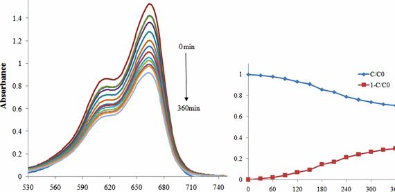
Figure 8 shows the photodegradation of methylene blue of samples. With growing lighting time, the degradation rates of methylene blue of samples elevated. After 60 min, the Mn/Ti-N-WACF-series were built with a greater degradation rate for methylene blue than Ti-WACF. After 240 min, the degradation rates for 33 mg/L methylene blue from the Mn/Ti-N-WACF-series arrived at 39%, 24%, 89%, and 93%. The degradation rate of methylene blue was not directly proportional towards the Mn doping content from the Mn/Ti-N-WACF-series. This result recommended that photocatalytic degradation isn’t just based on the visible light absorption performance, but additionally by additional factors, like the electron-hole recombination rate and loading amount. It had been also discovered that all the Mn/Ti-N-WACF-series show enhanced photocatalytic degradation of MB than the commercial P25 [ 43 ], and also the photocatalytic degradation of Mn/50Ti-N-WACF samples for MB still arrived at as much as 90% following the same experiment was transported out 3 occasions. Furthermore, all of the Mn/Ti-N-WACF-series samples demonstrated significant visible light responsive activities for that degradation of MB when compared with TiO2 powder, because of WACF being their carrier.
Photodegradation under visible light of methylene blue (MB) of samples.
Mn/N co-doped TiO2 loaded on wood-based activated carbon fibre (Mn/Ti-N-WACF) were effectively made by sol–gel and impregnation method. Mn/N co-doping could enhance the loading rate of TiO2 around the Mn/Ti-N-WACF surface. With growing Mn doping content, the TiO2 diameter of Mn/Ti-N-WACF was decreased after which elevated. The Ti content of Mn/Ti-N-WACF was greater compared to Ti-WACF, and decreased with growing Mn doping content. Additionally, N within the Mn/Ti-N-WACF samples substituted a few of the O atoms within the TiO2 lattice. The bandgap width from the Mn/Ti-N-WACF samples was slightly smaller sized compared to Ti-WACF due to the Mn/N co-doping. This stimulated the photocatalytic activity from the Mn/Ti-N-WACF samples for methylene blue degradation under visible-light irradiation.




 William cronon changes in the land thesis writing
 Writing the bachelor thesis samples
 Construction management topics for thesis writing
 Adwait ratnaparkhis 1998 thesis writing
 Olga veksler phd thesis proposal
