Our Guarantees Our Quality Standards Our Fair Use Policy
How Come United kingdom Essays Different?
- There is a verifiable exchanging history as being a United kingdom registered company (details within the finish of every page).
- Our Nottingham offices are suitable for purchase to everybody to satisfy we greater than 40 full-time staff.
- United kingdom Essays partner with Feefo.com to produce verified customer testimonials – both positive and negative!
Ask an expert FREE
Ask an expert Index Ask an issue Compensated Services
About Our Ask an expert Service
Our free of charge “Ask a specialistInch Service enables users to get a solution as much as 300 words for the academic question.
- Questions typically clarified within 24 hrs.
- All solutions are researched and printed by properly accredited academics within the question’s market.
- Our services are totally private, only the solution is printed – we never publish your very own details.
- Each professional answer includes appropriate references.
About Us
More Details On Us
Printed: 23, March 2015
This project is unquestionably the simulation and implementation of multilevel inverter given induction motor drive. The output harmonic posts are reduced by using multilevel inverter. The multilevel inverter is build while using the PIC 16f877A microcontroller to provide the signal into motor driver that may separate everywhere current for that power Mosfet. There’s a six power Mosfets which accustomed to the inversion from Electricity battery current to Ac current. In symmetrical circuit, the current and power increase with the rise in the amount of amounts of inverter.
The switching position for the pulse is chosen such method of reduce the harmonic distortion. This drive system has advantages like reduced total harmonic distortion and greater torque. The type of the multilevel inverter technique is developed with SVM approach to control the induction motor. The experimental results coincide with simulation results.
This project aims to provide an easy model like using power MOSFET that controlled by PIC microcontroller to show that inversion is possible. Another topologies of multilevel inverter like uneven hybrid cells and soft-switched multilevel inverters will most likely be discussed in literature review. This project also presents relevant control circuit and literature review on other inverter circuits and modulation ways of develop using this quantity of converters for example multilevel sinusoidal pulse width modulation, multilevel selective harmonic elimination, and space-vector modulation. There are many applications for the inverter for example in laminators, conveyor belts, and unified power flow controllers. Involve active circuit in-front finish within the input side for individuals inverters offering regenerative loads can also be discussed within the literature review or review, along with the circuit design can also be presented within the later chapter.
Professional
Have the grade
or possibly reimbursement
using our Essay Writing Service!
Essay Writing Service
Figure 1.1 – The block diagram of overview of the task.
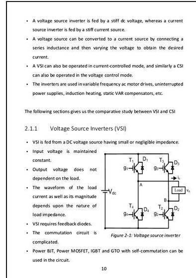
From Figure 1.1, it’s observed the facility current arises from the ability way of getting 12V battery. The current is first reduces to 5V to provide PIC. A variety of it supply for that inverter but controlled by PIC microcontroller. The PIC used is 16F877A which generates numerous pulse then provided to the motor driver. When the visits the introduction of motor driver, the MOSFET begin to invert the middle beat in order appear like the AC current inside the output.
1.5 Objectives
The objectives within the project are:
’ Producing the AC output current by inverting the 12V Electricity current.
’ Creating a staircase AC waveform inside the inverter output.
’ The wave must manage to switch on the AC motor or control the AC motor.
To create an inverter using Mosfet.
To lessen the harmonics content within the inverter output.
To boost the current and output within the inverter employing a multilevel technique.
To operate the induction motor together with your multilevel inverter.
By using this report chapter 2 may be the literature review. The chapter discuss the idea of current technology on multilevel inverter.
Chapter 3 is methodology. This chapter discuss the way the job planning. Flow chart enables you to let you know that a task will most likely be completed rapidly. Actual circuit used and components used can also be mentioned during this chapter.
Chapter 4 may be the presentation of experimental data. This chapter presents try current and waveform measurement in the introduction of the circuit. Some technical explanation will most likely be proven during this chapter.
Chapter 5 could be a discussion on prototyping chapter. This chapter displays the prototype within the project. Many photos will most likely be proven during this chapter. Problem facings also discussed during this chapter.
Chapter 6 could be a conclusion and future recommendation across the project. This chapter concludes experimental works, testing and within the project. The chapter also mention advantages and disadvantages for your work. Future recommendations at work improvement are available under this chapter.
Chapter 2: LITERATURE REVIEW
2. Multilevel inverter technology
Within the 21 century, many heavy industries have commerce to demand greater power electrical equipment, that are now achieve the Giga level. Many controlled ac drives within the megawatt range are actually still designed for purchase with limitation across the number and they also usually attached to the medium-current networking, which mean 1000V to 10kV possibly. Today, it is sometimes complicated for engineer enabling you to connect just one power semiconductor switch to control the medium current grids for example (2.3, 3.3, 4.16, or 6.9 kV) [19]. Due to these reasons, a totally new quantity of multilevel inverters have invented because the solution for utilized in medium to greater current levels [1]-[3].
Comprehensive
Plagiarism-free
Always rapidly
Marked to plain
Multilevel inverters imply they normally use a number of power semiconductors and capacitor as being a current source along with the growth and development of which make the voltages with walked waveforms which look like staircase. The commutation presently developed in ways it enables switches adding more capacitor voltages, that may achieve extreme high current inside the output, since the task within the power semiconductors are merely reduced the voltages. Figure 2. proven a schematic diagram on among the particular phase lagging of inverters with some other figures of levels, that the act of power semiconductors is symbolized having a perfect switch added with several positions [4].
Figure 2. – Difference lagging within the inverters. [19]
A Few-level inverter as proven in (a) of Figure 2. can generates an output up-to-date with two current values (levels) which respect for that negative terminal within the capacitor [19]. The 3-level inverter however generates three voltages, and so forth [19].
To discover the way the inverter work, let us keep in mind that there’s the amount of stages in the phase current seems across the negative terminal within the inverter, so the amount of stages in our backward and forward phases within the load a is [19]
then when there’s numerous steps b within the phase current of three-phase load in wye connection is supplied by [19]:
The word of multilevel start with three-level inverter which introduced according to Nabae et al. [19]. Using the theory, by growing the amount of levels within the inverter, the output voltages can get to get more steps and so developing a staircase waveform, approaching sine wave which reduced the harmonic distortion [19]. However, if the amount of levels is increases, so the control circuit complexity and current imbalance problems can occur. This cannot eliminate around this greater level [19].
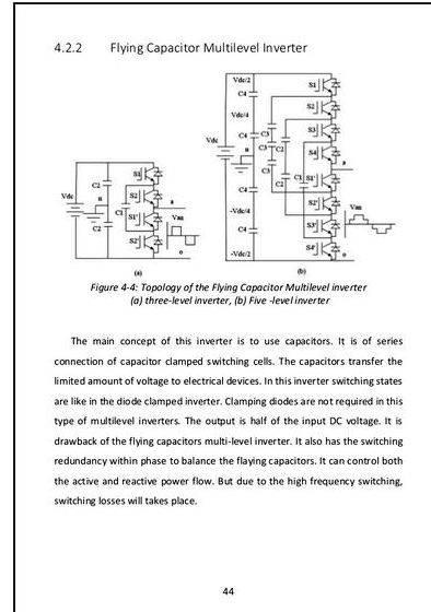
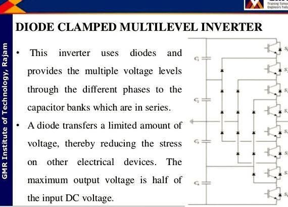
You will find three different circuits are really suggested during this modern multilevel inverter. They’re: diode-clamped (neutral-clamped) [4], capacitor-clamped (flying capacitors) [1], [5], [6] and cascaded multicell which separate electricity sources [1], [7]-[9]. In addition, several modulation techniques and control circuits are really built or produced for multilevel inverters including: multilevel sinusoidal pulse width modulation (PWM), multilevel selective harmonic elimination, and space-vector modulation (SVM) [19].
The symbol of multilevel inverters are the following:
’ The inverter can produces output voltages with low noise or distortion [19].
’ They draw high input current without distortion [19].
’ They produces smaller sized sized sized common-mode (CM) current, thus cuts lower round the stress within the
motor bearings. Also, while using the sophisticated modulation methods, CM voltages
may be eliminated [8].
’ They might sustain in low switching frequency [19].
In a number of patents search, the outcome show multilevel inverter circuits actually are really invented around greater than twenty five years approximately. The initial patent across the inverter arrived on the scene in 1975 [9], by which then adopted by cascade inverter that was first defined while using the format that connects individually while using the electricity-sourced full-bridge rectifier circuit in series to synthesize the staircase ac output current. While using manipulation within the cascaded inverter, we’re able to understand that the diodes block the sources and clamped output variation current [10]. Many individuals call the diode-clamped inverter because the neutral-point clamped (NPC) inverter in individuals days it had been present in a 3-level inverter while using the mid-current level that was looked as the neutral point. Since the NPC inverter can effectively doubles the current level without requiring precise current matching, so the circuit has become won noisy . of 1980s. While using NPC inverter now’s extensively can be found in [11].
Because the cascade inverter was invented, now its applications still not prevail available on the market before the mid of 1990s. Two important patents [12], [13] develop to point out the helpful of cascade inverters drive an automobile the motor and make use of in utility applications. Because of there as being a great requirement of medium to high-power inverters, the cascade inverter now becomes tremendous interesting even until today. Several patents also found for the applying cascade inverters within the regenerative-kind of motor drive [14]-[16]. U.S has invented many multilevel inverters. The registration for U.S. submit the multilevel inverter for patents, that have been the capacitor-clamped multilevel inverters, demonstrated in the 1990s[17], [18]. Now, the multilevel inverters are utilized extensively in high-power applications under medium current levels. The applications include using laminators, mills, conveyors, pumps, fans, blowers, compressors, and etc.
2.1 Diode clamped inverter
This Essay is
TRISB = 0x00 // PORTB is output
TRISD = 0x00 // PORTD is output
Understand that the happy couple of lines within the program are widely-used to define the input and output port. This is often proven below:
Understand that analogue input is define as ANSEL = 0x01 and input port is TRISA = 0xFF and output port is TRISB and TRISD which initially set to 0x00. Initializing the main harbour is essential prior to the actual program send and acquire the command. This program enables you to disseminate the pin configuration or identify in which the signal should goes after processing.
PORTB =
Delay_ms(1000)
PORTB = 0xFF
Delay_ms(1000)
PORTB =
Delay_ms(1000)
Setting the delay to deal with signal is proven within the below coding:
The above mentioned pointed out stated command is essential to make certain there’s no overlap within the signal seems inside the output.
while (1)
current = ADC_Read()*.0048 *5.6 //read current from battery
//Output at Port B to point out current level
if (current = 8)
PORTB = 0x80
PORTB = 0x80




 Bboy lilou vs thesis writing
 Slavery and the making of america thesis writing
 Ust medical technology thesis proposals
 Harvard style of thesis writing
 Thesis writing meme for authors
