Our Guarantees Our Quality Standards Our Fair Use Policy
What Makes UK Essays Different?
- We have a verifiable trading history as a UK registered company (details at the bottom of every page).
- Our Nottingham offices are open to the public where you can meet our team of over 40 full-time staff.
- UK Essays partner with Feefo.com to publish verified customer testimonials – both good and bad!
Ask an Expert FREE
Ask an Expert Index Ask a Question Paid Services
About Our Ask an Expert Service
Our totally free “Ask an Expert” Service allows users to get an answer of up to 300 words to any academic question.
- Questions typically answered within 24 hours.
- All answers are researched and written by fully qualified academics in the question’s subject area.
- Our service is completely confidential, only the answer is published – we never publish your personal details.
- Each professional answer comes with appropriate references.
About Us
More About Us
Published: 23, March 2015
Abstract- In this paper, the Hot Carrier Injection (HCI) characteristic for a triple gate bulk FinFET is investigated through modeling the HCI generated substrate current, electric field distribution and the maximum electric field near the drain region. Then an analytical model for HCI induced trap generation and degradation in this structure is presented. The model is obtained by solving the Reaction-Diffusion equations multi-dimensionally. The geometry dependence of the time-exponent of HCI degradation in this structure is modeled in the framework. The accuracy of the models is verified using experimental results.
Keywords: Hot Carrier Injection, Triple Gate Bulk FinFET, Impact Ionization, Substrate Current, Reaction-Diffusion (R-D) model.
As MOSFET devices are scaled down to nanometer regime, because of the high lateral electric field, the short-channel effect becomes more severe reducing the gate control on the channel. In order to suppress this effect, bulk FinFETs which are built on bulk Si wafers, are introduced and recognized as one of promising structures to be utilized in nanoscale CMOS technology [1]-[3]. The bulk FinFETs have the same scalability as SOI FinFET, lower defect density, lower wafer cost, and higher heat transfer rate in compare to SOI FinFETs [4]. Also these structures have less back bias effect than conventional MOSFETs [3].
Professional
Get your grade
or your money back
using our Essay Writing Service!
Essay Writing Service
Hot Carrier Injection is the dominant reliability concern in nanoscale NMOSFET devices. This phenomenon is the result of accelerating of inversion electrons in high electric field of the channel saturation region. If these accelerated carriers gain sufficient energy can cause impact ionization near the drain region and generate electron-hole pairs. In an NMOSFET, the generated electrons increase the drain current and if can injected in the oxide, giving rise to gate leakage current. The holes generated by impact ionization flow out of the substrate contact and constitute substrate current. So traditionally the measured substrate current has been used to characterize the HCI degradation [5]. Some of these energetic electrons may obtain enough energy to create traps by breaking Si-H and Si-O bonds at the Si/Oxide interface of MOSFET device.
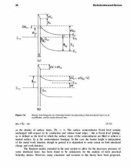
These generated interface traps lead to degradation of important parameters of the device such as threshold voltage, saturation current and transconductance of the device. As a result, HCI is a dominant factor which limits the NMOSFET lifetime [5], [6].
The classical Reaction-Diffusion (R-D) model is the framework which can be used to describe the trap generation during NBTI and HCI phenomena [7]. In planner MOSFET devices, the HCI generated interface traps can be estimated using the two-dimensional (2-D) solution of R-D equations. But in novel device structures such as triple gate bulk FinFETs, it is necessary to solve these equations multi-dimensionally to find the time evolution of HCI effect. Recently, in [8], a geometry dependent method for solving the R-D equations is presented. The method can be used to model the HCI effect in novel devices with different structures. The results of this method show that the geometry and the structure of the device can affect the time dependence of the trap generation rate [8]. Modeling efforts on HCI induced degradation have been mainly concentrated on conventional bulk NMOSFET devices [5], [9]. To the best of our knowledge, there have been a few studies on modeling of the HCI generated substrate current in triple gate bulk FinFETs [10], and there is not any comprehensive model for HCI generated interface traps and degradation in novel device structures such as triple gate bulk FinFETs.
In this study the HCI generated substrate current of a triple gate bulk FinFET is modeled and analyzed through solving the Poisson’s equation in the saturation region near the drain for obtaining the electric field distribution and the maximum electric field near the drain region. For these modeling nth power law MOS model is used to obtain the saturation current of the short channel device. Then multi-dimensional method of solving the R-D equation [8] is used to develop a compact and analytical model for the interface trap generation during HCI stress in a triple gate bulk FinFET for the first time. Also, the time-exponent of the trap generation is obtained considering the geometry of the device and the HCI degradation dependence on fin width of the device is investigated. The rest of the paper is organized as follow. In Section 2, the HCI induced substrate current model for triple gate bulk FinFET is explained. In Section 3 the proposed analytical model for HCI induced trap generation and degradation of saturation current of the device is presented while in Section 4, the results are discussed. The paper is concluded in Section 5.
Comprehensive
Plagiarism-free
Always on Time
Marked to Standard
MODELING OF SUBSTRATE CURRENT
Substrate Current Model Development
Traditionally, HCI degradation is characterized using measurement of substrate current which is induced by hot carriers [5]. So it is essential to have an analytical model for substrate current of the device. In order to drive an analytical model for substrate current in a triple gate bulk FinFET, we need to solve Poisson’s equation in the saturation or impact ionization region of the channel as shown in Fig. 1 [11]. Solving this equation leads to electric field distribution in the saturation region and as a result is used to find impact ionization rate and the amount of the substrate current.
To simplify our analysis, we assume that the vertical field at the bottom boundary is negligible. Also to remove the need for a 2-D integral, we approximate the slope of electric field at y and z direction as constant. So one can write [12]
Where tox is the oxide thickness, H and W are the height and width of the fin, V(x) is the potential value in the x point of the channel, Vfb is the flat band voltage and φF is the Fermi level potential at the fin and is equal to
In (4), Na is the doping concentration in the fin of the device. The Poisson’s equation in the impact ionization region can be writen as
Figure 1. The impact ionization region of a triple gate bulk FinFET [11]
Nm is the total mobile carriers in the saturation region. based on the previuos assumptions we have
At the velocity saturation point (x=0), (6) can be written as
Subtracting (7) from (6) and using V(0)=Vdsat. one can write
Where l is the characteristic length of triple gate bulk FinFET and is equal to
Using (8) and the boundary condition of. and. one can find the potential distribution, electric field distribution and the impact ionization region length ∆L as
Where Vsat is equal to Vg-Vth. With assumption of having the maximum electric filed at the drain edge of the channel and, the maximum electric field at the channel is equal to
η is a dimensionless fitting parameter which is between 0 and 1 and is used for modeling short channel effect. This parameter is extracted using experimental results.
The impact ionization rate in a MOSFET device can be expressed as
Where Ai (cm-1) and Bi (V/cm) are ionization constants. As can be seen in (10) and (11), the electric field in saturation region increases exponentially, so according to the nonlocal energy balance model, the energy of electrons lags behind the electric field [13]-[15]. So the effective electric field in the impact ionization rate is smaller than the maximum field in saturation region. In order to modeling the nonlocal effect, l0 parameter which is the energy relaxation length is used and the effective electric field can be written as [10]
The reduced field can be modeled as the increased ionization constant [10]
Narrow width S/D extension regions of a FinFET device caused high parasitic resistance (Rpar) as shown in Fig. 2 and so the effective drain voltage drops across this region from the contact to junction. This effect can decrease the maximum electric field as
The effect of these parasitic resistances on decreasing the electric field can be modeled as the increased ionization constant [10]
Parameter S can be found using experimental results. The substrate current can be obtained through integrating the impact ionization rate over the saturation region of the channel [16] and can be written as
In order to obtain the substrate current from (19), there is a need to an anlytical model for saturation current (Idsat) of the triple gate Bulk FinFET device. For this purpose nth power law MOS model [17] is used. Following this model, the saturation current of a short channel MOS device can be expressed as
Where Vth is the threshold voltage of the device and Weff and Leff are the effective width and length of the channel. B and n are constants which describe the short-channel effects in an empirical manner and will be extracted using experimental results. For a triple gate FinFET, the channel effective width is equal to W+2H. Usually crystal orientation of the top surface in a triple gate transistor is and the side surface is . So the channel direction is lt;110gt;. The mobility ratio of the to the surface is about 1.67 [18]. We model this ratio in the effective channel width of the device, so (20) can be rewritten as
This Essay is
This essay has been submitted by a student. This is not an example of the work written by our professional essay writers.
Examples of our work
Figure 2. Parasitic resistance (Rpar) of the Narrow width S/D extension regions of a FinFET device [10]
Using (19) and (21), one can obtain the amount of HCI generated substrate current in a triple gate bulk FinFET.
Extraction of Substrate Current Model Parameters
In order to finding the substrate current model, first we must obtain the parameters of saturation current model. These parameters are extracted from experimental results for a triple gate bulk FinFET device with a gate length of 80 nm, the oxide thickness of 1.5 nm, the Fin width of 40 nm and Fin height of 100 nm presented in [20]. The values of the extracted fitting parameters are given in Table I.
Saturation drain current characteristic of the mentioned device is shown in Fig. 3. The applied drain bias is 1V. As the figure shows, the results obtained from the analytical model (21) are in good agreement with the measured data [20]. The average error is approximately 4.2%.
The fitting parameters of substrate current model are extracted from experimental results for the mentioned device presented in [20]. The values of the extracted fitting parameters are given in Table II.
Substrate current characteristic of the mentioned device are drawn in Fig. 4. The applied drain bias is 2V. As the figure shows, the results obtained from the analytical model (19) are in good agreement with the measured data. The average error is approximately 4%.
As can be seen in the figure, the maximum substrate current occurs in mediate gate voltages. Then with an increase in the gate voltage, Vdsat increases and as a result the maximum electric field in impact ionization region decreases which leads to deacrease in substare current.
TABLE I. SATURATION CURRENT MODEL PARAMETERS
Figure 3. Saturation drain current characteristics
TABLE II. SUBSTRATE CURRENT MODEL PARAMETERS
Figure 4. Substrate current characteristic
MODELING OF TRAP GENERATION DURING THE HCI STRESS
During HCI stress some of the generated energetic electrons may obtain enough energy to create traps by breaking Si-H and Si-O bonds at the Si/Oxide interface of MOSFET device [19]. The generation of traps, shifts the threshold voltage during HCI stress using based on
As described in Section 2, traditionally HCI stress is characterized using measurement of substrate current that is induced by hot holes [5]. But in nanoscale devices the other leakage components such as gate leakage, junction leakage and GIDL become dominant which result in a significant deviation of measured substrate current from (19). This phenomenon made usage of substrate current ineffective for describing HCI degradation in nanoscale regime [21].
Although NBTI and HCI phenomena are different in many aspects, they both are the result of Si-H bond breaking at silicon and oxide interface and then diffusion of generated hydrogen atoms to the gate. So both of them can be modeled using Reaction-Diffusion (R-D) framework [22]. The main differences between NBTI and HCI phenomena are the rate and mechanism of generation of the traps, the local trap generation near the drain edge and the diffusion of generated hydrogen atoms along the channel in the HCI phenomena which make this diffusion a 2-D problem. In this section we used the R-D framework to develop an analytical model for trap generation during HCI stress in a triple gate bulk FinFET.
Using the R-D model, the rate of generation of the interface traps and the diffusion of hydrogen are given by, respectively [23]
Where N0 is the initial volume concentration of the Si-H bonds, NH is the volume concentration of hydrogen atoms at the interface, kF is the forward reaction rate, kR is the reverse reaction rate, and DH is the hydrogen diffusion coefficient.
When the stress is applied, at the beginning, the trap generation is slow. As a result, in this phase, dNIT/dt ≈ 0 and NIT lt;lt; N0, and hence, (23) can be written as [24]
In planner MOSFET, the diffusion of HCI generated hydrogen atoms through the gate oxide and channel, described by (24), may be considered as a 2-D problem while in 3-D structures, such as triple gate FinFETs, the diffusion through the corners should be treated as a 3-D problem. Hydrogen profiles for 1-D, 2-D, and 3-D diffusion through gate oxide are shown in Fig. 5 [8].
Figure 5. Hydrogen profile for (a) 1-D, (b) 2-D, and (c) 3-D diffusion [8]
At the interface, the release of every hydrogen atom generates one interface trap. Therefore, the total density of the interface traps may be obtained from [8]
Using the hydrogen diffusion profiles in the oxide shown in Fig. 5, the amount of the generated interface traps in the case of 1-D, 2-D, and 3-D may be obtained from, respectively [8]
Where is the diffusion length of the hydrogen atoms in the oxide.
Fig. 6 shows the cross section of the triple gate FinFET device which indicates that the HCI generated hydrogen diffusion in three channels is 2-D, but in the corners is 3-D [8].
Figure 6. Diffusion of hydrogen atoms in the five regions of a triple gate FinFET
Using (28) and (29), the amount of HCI generated interface traps in a triple gate bulk FinFET can be expressed as
Using (25) and (30), one can write
The parameter kF depends on the inversion charge at the interface (Qi), the probability of these electrons travelling a sufficient distance in the high lateral electric field (Em) of impact ionization region to gain energy φit or more without suffering a collision [5], the ability of these charges to tunnel to the Si-H bonds which depends exponentially on the vertical electric field at the interface (EOX), the capture cross section of Si-H bonds (σ0), and other field dependent causes of Si-H bonds breaking [23]. Thus this parameter can be written as
Where in (32) λ is the mean free path of the electron. DH depends on the temperature. The temperature dependences of DH, kF, and kR can be modeled by the activation energy (Ea) of Si-H bond and is given by [23].
Therefore, using (31)-(33), the trap density at the interface of the device fin and the oxide for triple gate bulk FinFET devices can be expressed as
RESULTS AND DISCUSSION
There are four fitting parameters in the developed HCI induced trap generation model which are KHCI, E0, D0 and Ea. They were extracted from experimental results for HCI induced degradation of saturation current in the mentioned device presented in [20]. Using (21) and (22), the degradation of saturation current induced by HCI generated interface traps is given by
Using (35) and the experimental results [20], the values of the fitting parameters can be extracted which is shown in Table III.
TABLE III. HCI GENERATED INTERFACE TRAPS MODEL PARAMETERS
The time evolution of HCI induced saturation current degradation for the mentioned device in previous section, is shown in Fig. 7. As the figure shows, the results obtained from the analytical model presented in (35) are in good agreement with the measured data [20]. The average error is approximately 2.5%.
The time-exponent of the saturation current degradation in Fig. 7 is approximately 0.565 and is larger than 0.5 which is the expected time exponent for the hydrogen diffusion in conventional single gate planner MOSFET structures [21]. The discrepancy between the expected and observed values is caused by the diffusion of hydrogen atoms through transistor corners. As previously mentioned, the diffusion through corners is a 3-D process. Considering this process in our derivation led to the second term in the developed model (34) which did not exist in the planner MOSFET device models and generates higher powers of time (tm, 0.5 ≤ m ≤ 0.75). So if we define the effective time-exponent (n) as, this second term cause a larger effective time-exponent for the trap generation and degradation of the device. The significance of the second term in (34) depends on the geometry of the device. A decrease in the fin width or its height increases the importance of the second term which leads to the increase of the effective time-exponent of the expression (n) and consequently the value of the generated traps (NIT) and degradation. The model results for the dependence of the effective time-exponent and the degradation of the saturation current on the device fin dimensions are shown in Fig. 8 and Fig. 9, respectively. In these figures, where the fin width and height are assumed to be the same and changed concurrently, the applied gate and drain voltages are 2.5V and the stress time is 1000s. As can be seen in these figures, the effective time-exponent is inversely proportional to the width and height of the fin and by increasing the width and height of the fin, the effective time-exponent and as a result the trap generation decreases which leads to less degradation of device parameters.
Figure 7. The time evolution of HCI induced saturation current degradation
Figure 8. The fin width dependence of effective time-exponent (n)
Figure 9. The fin width dependence of the shift in threshold voltage
In this work, the HCI characteristics for a triple gate bulk FinFET were investigated through modeling the HCI generated substrate current, electric field distribution and the maximum electric field near the drain region. Then we presented an analytical model for HCI induced trap generation and degradation in a triple gate bulk FinFET. It was based on solving the Reaction-Diffusion equations multi-dimensionally considering the atomic diffusion of hydrogen in the oxide. The model was dependent on the geometry of the structure. It included the geometry dependence of the HCI degradation time-exponent in triple gate bulk FinFET device. The model results for saturation current degradation matched very well to the experimental results. Also, the results showed that there were larger effective time-exponent for this structure in comparison with that of the planner MOSFET devices.
Request Removal
If you are the original writer of this essay and no longer wish to have the essay published on the UK Essays website then please click on the link below to request removal:
More from UK Essays




 Friction stir processing thesis proposal
 Master thesis proposal finance calculator
 Saskia sassen global city thesis proposal
 Dissertation proposal sample uk will
 Fourth generation warfare thesis proposal
